Review
. 2018 Sep 6;18(9):2973.
doi: 10.3390/s18092973.

Helical Structures Mimicking Chiral Seedpod Opening and Tendril Coiling

Affiliations
Review

Helical Structures Mimicking Chiral Seedpod Opening and Tendril Coiling

Guangchao Wan et al. Sensors (Basel). .

Abstract

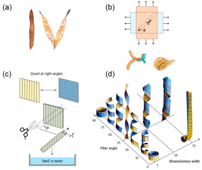
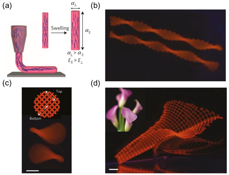
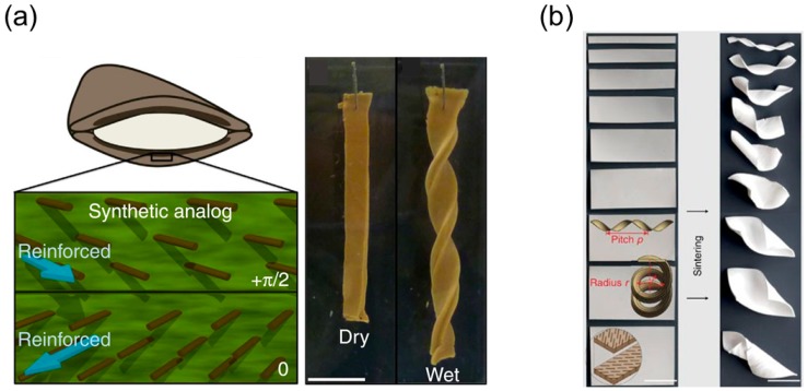
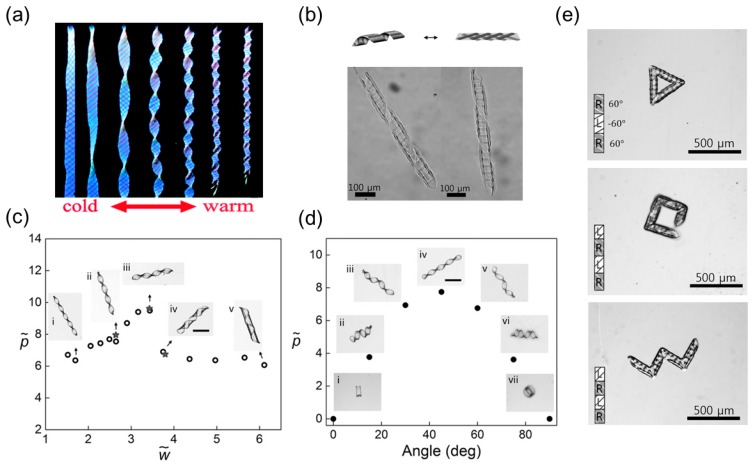
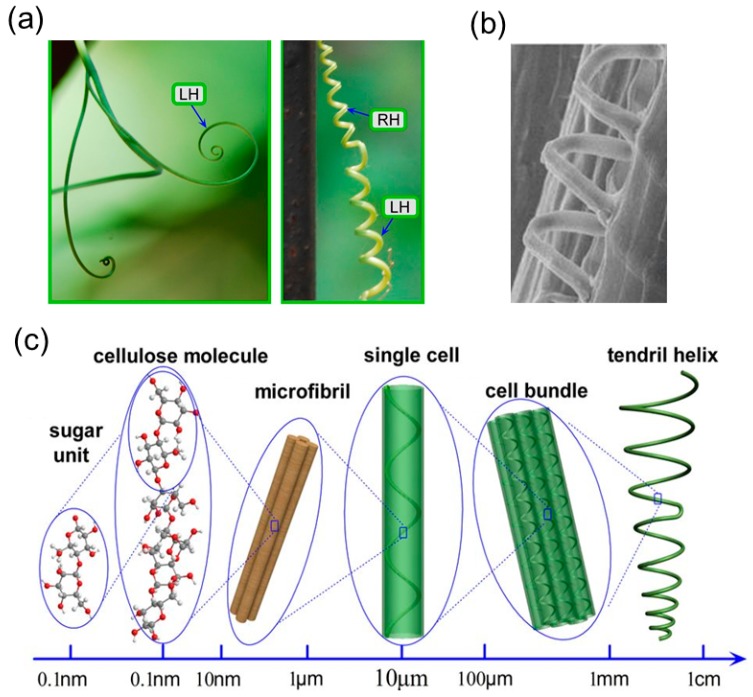
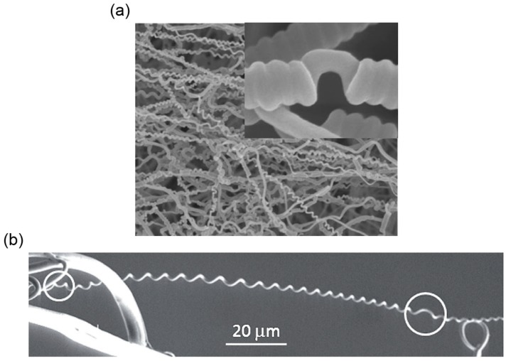
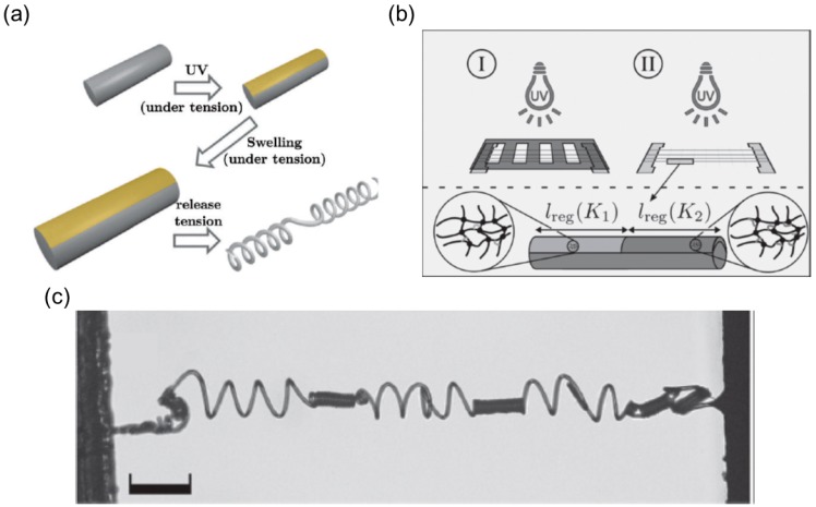
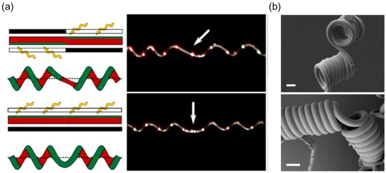
Helical structures are ubiquitous in natural and engineered systems across multiple length scales. Examples include DNA molecules, plants' tendrils, sea snails' shells, and spiral nanoribbons. Although this symmetry-breaking shape has shown excellent performance in elastic springs or propulsion generation in a low-Reynolds-number environment, a general principle to produce a helical structure with programmable geometry regardless of length scales is still in demand. In recent years, inspired by the chiral opening of Bauhinia variegata's seedpod and the coiling of plant's tendril, researchers have made significant breakthroughs in synthesizing state-of-the-art 3D helical structures through creating intrinsic curvatures in 2D rod-like or ribbon-like precursors. The intrinsic curvature results from the differential response to a variety of external stimuli of functional materials, such as hydrogels, liquid crystal elastomers, and shape memory polymers. In this review, we give a brief overview of the shape transformation mechanisms of these two plant's structures and then review recent progress in the fabrication of biomimetic helical structures that are categorized by the stimuli-responsive materials involved. By providing this survey on important recent advances along with our perspectives, we hope to solicit new inspirations and insights on the development and fabrication of helical structures, as well as the future development of interdisciplinary research at the interface of physics, engineering, and biology.

Keywords: biomimetic; helical structures; perversion; seedpod opening; stimuli-responsive materials; tendril coiling.


Conflict of interest statement

The authors declare no conflict of interest.

Figures

Figure 1
Figure 1
The opening mechanism of Bauhinia variegate’s pod. (a) A closed seedpod in a wet environment (left) and the opened seedpod in a dry environment (right); (b) Mechanical analog of seedpod opening by attaching two uniaxially stretched elastomer sheets together and cutting a ribbon at an angle θ with width w (top). The bilayer sheet adopts a saddle shape: schematic illustration (bottom left), experiment (bottom right); (c) The process to generate helices using a bilayer paper sheet reinforced with fibers; (d) Design space for helix generation with respect to the fiber angle and the dimensionless width. (a,b) are from [11], reprinted with permission from AAAS; (c,d) are from [22], reprinted with permission from AAAS.
Figure 2
Figure 2
Humidity-responsive hydrogel-based helical structures mimicking Bauhinia variegata. (a) Shear-induced alignment of cellulose fibrils along the printed filament (left) and anisotropic swelling of the printed filament (right); (b) Helical shape generated by 4D-printed hydrogel; (c) Saddle shape (bottom) from orthogonal patterns of filaments in two layers (top), the scale bar is 2.5 mm; (d) Biomimetic lily flower from 4D-printed hydrogel, the inset is the lily flower in nature and the scale bar is 5 mm. (ad) are from Ref. [26], reproduced with permission, copyright 2016 Nature Publishing Group.
Figure 3
Figure 3
Humidity-responsive hydrogel-based helical structures mimicking Bauhinia variegata, the reinforcement’s distribution is controlled via magnetic field. (a) Microplatelet alignment in a bilayer sheet (left, schematic) mimicking Bauhinia variegata and shape transformation of the synthesized hydrogel in water (right). The scale bar is 1 cm. (b) Microplatelet-induced shape transformation of ceramics from a planer sheet (left) to a helical shape (right) after sintering, the radius and pitch of the helix are influenced by the ribbon’s width from top to bottom (right). The scale bar is 25 mm; (a) is from [27], reproduced with permission; (b) is from [65], reproduced with permission, copyright 2013 Nature Publishing Group.
Figure 4
Figure 4
Thermally responsive hydrogel-based helical structures mimicking Bauhinia variegata. (a) Transition from a twisted helicoid to a spiral helical shape as the shrinkage ratio of hydrogel increases with rising temperature; (b) Schematic illustration of helical transformation in a tri-layer hydrogel composite (top) and a helical hybrid hydrogel with right-handedness (bottom left) or left-handedness (bottom right) under an optical microscope; (c) The relationship between the helix pitch and the dimensionless width; (d) The relationship between the helix pitch and the reinforcement angle; (e) Complex shapes obtained by connecting helices with different lengths or handedness, including triangle (top), square (middle) and zigzag (bottom). The insets are 2D precursors of the hydrogel sheets during photo-crosslinking. (a) is from [28], reprinted with permission from The Royal Society of Chemistry; (be) are from [29], reprinted with permission from 2017 Wiley.
Figure 5
Figure 5
pH-responsive hydrogel-based helical structures mimicking Bauhinia variegata. (a) Schematic illustration of the three-step photo-crosslinking of PAA/PNIPAm hybrid composite guided by a photomask. The green strips are PAA while the grey part is PNIPAm. The photomask is made by drawing black lines; (b) Shape transformation of P(VI-co-AAM)-PNIPAm-PAA hybrid hydrogel when pH changes from 9 to 1. The brown, grey and green parts are P(VI-co-AAM), PNIPAm and PAA, respectively. The upper array shows the strip orientations in the top and bottom layers. The schematic (bottom) and experimental (top) figures of shape transformation are both shown together in the middle and bottom array. The scale bar is 1 cm (a,b) are from [30], reprinted with permission from The Royal Society of Chemistry.
Figure 6
Figure 6
Nematic configurations and formation of helix/spiral induced by temperature variation. (a) Planar-, vertical-, hybrid-, and twist-nematic configurations of LCNs; (b) Formation of a helicoid ribbon from narrow TNE film at 330 K; (c) Inverse of the twist pitch (1/pT) as a function of normalized temperature (T/TNI, where T is temperature and TNI is the nematic-isotropic transition temperature). Positive and negative pT indicate left- and right handedness, respectively. Red circles and blue squares represent data of L- and S-geometry, respectively. Filled symbols indicate data obtained in cooling processes and open in heating processes. Theoretical predictions are represented by lines; (d) Formation of a spiral ribbon from the wide TNE film at 336 K; (e) Inverse of the helical pitch (1/ph) and the diameter (1/d) as a function of T/TNI. Positive and negative pH indicate left- and right handedness, respectively. Red circles and blue squares represent data of L- and S-geometry, respectively. Filled symbols are data for 1/d and open symbols are data for 1/ph. Theoretical predictions are represented by lines; (f) Various simulated helical shapes corresponding to different off-axis angles. Simulation performed by Vianney Gimenez-Pinto. (θ). Figures reprinted from: (a) [85], with permission from Elsevier; (be) [31]; (f) [32], with permission from the American Physical Society.
Figure 7
Figure 7
Light-induced helical motion of a LCN ribbon. (a) Change in pitch and inversion of handedness of spiral ribbons cut at different angles (φ) irradiated by UV light; (b) Anisotropic deformation at the molecular level: shrinkage along the director and expansion in the direction perpendicular to the director; (c) A proof-of-principle for an actuator capable of performing complex motion: the kink in the middle connecting helices of opposite handedness shows a smooth push-pull motion. Figure reprinted from [38] by permission of Springer Nature.
Figure 8
Figure 8
Formation of a helical shape triggered by other stimuli. (a) TNE ribbon in air, THF liquid, and THF vapor; (b) TNE ribbon remaining flat in air and curling into a helicoid and a self-contacting helix in THF vapor as a function of time; (c) A bilayer LCN ribbon, in which the director is 45° to the long axis of the ribbon, showing left-handedness when dried and right-handedness when wet; (d) A bilayer LCN ribbon, in which the director is −45° to the long axis of the ribbon, exhibiting a smooth transition in shape from flat to curled as humidity decreases. Figures (a,b) reprinted from [40] with permission from Elsevier; (c,d) from [41], with permission from the American Chemical Society.
Figure 9
Figure 9
Formation of a helical shape triggered by water/acetone. (a) Ribbons cut at different angles (A: 0°; B: 22°; C: 45°) on a single-layer LCE film where the director is in the horizontal direction; (b) Formation of different helically coiled shapes of A, B and C in response to water exposure. Figure reprinted with permission from: (a,b) reference [42], American Chemical Society.
Figure 10
Figure 10
Shape memory polymers-based helical structures mimicking Bauhinia variegata. (a) Schematic illustration of the fabrication process of the shape memory elastomeric composite; (b) Experimental images of the coiled bilayer composites after heat treatment. The left-top corner of each image shows the tilting angel and the scale bar is 4mm. (a,b) are from [44], reprinted with permission from The Royal Society of Chemistry.
Figure 11
Figure 11
Coiling mechanism of Towel Gourd tendrils. (a) Towel Gourd tendril coils into a spiral shape with left-handedness before it touches a support (left) and forms a perversion connecting the right-handed and left-handed sections once it attaches to a support (right). ‘LH’ and ‘RH’ represent left-handed and right-handed, respectively; (b) Image of helical cellulose fibril inside cell’s matrix under scanning electron microscope; (c) Hierarchical chirality inside Towel Gourd tendril from the molecular level to the macroscopic shape. (ac) are from [12], reprinted with permission from Nature Publishing Group.
Figure 12
Figure 12
CNT-based helical structures mimicking Towel Gourd tendrils. (a) Groups of scanning electron images showing the fabrication process of the hierarchical helical fibers based on twisting MWCNTs. first row: dry-spinning (left, scale bar 500 μm, primary fiber (middle, scale bar 10 μm) and the nanoscale gaps between MWCNTs (right, scale bar 500 nm). Second row: bundle of primary fibers (left, scale bar 200 μm), twisted primary fibers (middle, scale bar 30 μm) and the microscale gaps between primary gaps (right, scale bar 2 μm). Third row: coiling of multi-ply primary fibers when twisting exceeds the threshold (left, scale bar 50 μm), hierarchical helical fiber (middle, scale bar 30 μm) and gaps inside HHF (right, scale bar 10 μm); (b) Hierarchical gaps, including microscale gaps between primary fibers and nanoscale gaps between MWCNTs, facilitate the solution’s infiltration; (a) is from [115], reprinted with permission from Nature Publishing Group; (b) is from [113], reprinted with permission from Nature Publishing Group.
Figure 13
Figure 13
Contractive actuation of the coiled secondary fibers made of MWCNTs under vapor and electric current stimuli. (a) The contraction actuation of the hierarchical helical fiber when getting close to the dichloromethane (left: schematic; right: experiments). d is the distance between the spring and liquid surface (scale bar 2 cm); (b) Electromechanical contraction actuation of a left-handed Kapton film with HHF inside; (a) is from [113], reprinted with permission from Nature Publishing Group; (b) is from [114], reprinted with permission from 2015 Wiley.
Figure 14
Figure 14
Formation of multiple perversions in a bilayer elastomer system. (a) Schematic illustration of the fabrication process of a bilayer elastomer with the misfit natural length; (b) The perversion’s number increases as h/w decreases (h/w= 4 (top), 2.7 (middle), 0.83 (bottom)); (a,b) are from [118], reproduced with permission, copyright: © 2014 Liu et al.
Figure 15
Figure 15
Mechanical properties of a helix with one perversion. (a) The tendril exhibits over-winding initially and then unwinds itself during pulling; (b) The phase diagram separating the unwinding and over-winding regimes in terms of elongation and η; (c) The Hooke’s constant of a scrolled SiGe/Si/Cr nanohelix with the normal or binormal cross-section under extension. (ac) are from [106], reproduced with permission from The Royal Society of Chemistry.
Figure 16
Figure 16
Schematic illustration of bi-component electrospinning setup and the internal structure of the electrospun fibers. (a) Schematic illustration of experimental setup of the bi-component electrospinning; (b) The schematic illustration of the off-centered, side-by-side and core-shell structure of the fiber. The blue and red represent different polymers. (a) is from [124], reprinted with permission, copyright (2015) American Chemical Society.
Figure 17
Figure 17
The electrospun fibers coil themselves with perversions. (a) Scanning electronic microscopy (SEM) image of TPU/Nomex nanofibers produced from side-by-side electrospinning; The inset shows a perversion inside the nanospring; (b) SEM image of the electrospun cellulose fibers, the perversion is underscored with white circles. (a) is from [127], reprinted with permission, copyright © 2009, John Wiley and Sons; (b) is from [128], reprinted with permission of Royal Society of Chemistry.
Figure 18
Figure 18
The electrospun fibers with further UV crosslinking. (a) Schematic illustration of the heterogenous structure induced by UV irradiation; (b) Schematic illustration of the two-step UV crosslinking in generating regions with different intrinsic curvatures; (c) Polarized light microscopy (POM) image of electrospun fibers separated by high-intrinsic-curvature regions and low-intrinsic-curvature regions. (a) is from [132], reprinted with permission, copyright © 2013, John Wiley and Sons; (b,c) are from [133], reprinted with permission, copyright © 2017, John Wiley and Sons.
Figure 19
Figure 19
The asymmetry and symmetry perversion in electrospun fibers under UV irradiation. (a) Left: schematic illustration of asymmetry perversion (top) and symmetry perversion (bottom) guided by the UV irradiation, right: experimental figures of asymmetry (top) and symmetry perversion (bottom). The perversion is pointed out by white arrows; (b) SEM images of the asymmetry (top) and symmetry perversion (bottom) in electrospun fibers. The scale bar is 10 μm. (a,b) are from [134], reprinted with permission from Nature Publishing Group.

Similar articles

Cited by

References

    1. Goldstein R.E., Goriely A., Huber G., Wolgemuth C.W. Bistable Helices. Phy. Rev. Lett. 2000;84:1631–1634. doi: 10.1103/PhysRevLett.84.1631. - DOI - PubMed
    1. Goriely A., Tabor M. Spontaneous Helix Hand Reversal and Tendril Perversion in Climbing Plants. Phys. Rev. Lett. 1998;80:1564–1567. doi: 10.1103/PhysRevLett.80.1564. - DOI
    1. Guo Q., Chen Z., Li W., Dai P., Ren K., Lin J., Taber L.A., Chen W. Mechanics of tunable helices and geometric frustration in biomimetic seashells. EPL (Europhys. Lett.) 2014;105:64005. doi: 10.1209/0295-5075/105/64005. - DOI
    1. Jung W., Choi S.M., Kim W., Kim H.Y. Reduction of granular drag inspired by self-burrowing rotary seeds. Phys. Fluids. 2017;29:041702. doi: 10.1063/1.4979998. - DOI
    1. Chattopadhyay S., Moldovan R., Yeung C., Wu X.L. Swimming efficiency of bacterium Escherichia coli. Proc. Natl. Acad. Sci. USA. 2006;103:13712–13717. doi: 10.1073/pnas.0602043103. - DOI - PMC - PubMed