

doi: 10.1038/s41598-018-31993-3.
Laser guided ionic wind
Affiliations
- PMID: 30202066
- PMCID: PMC6131152
- DOI: 10.1038/s41598-018-31993-3
Item in Clipboard
Laser guided ionic wind
Sci Rep.
.
Abstract
We report on a method to experimentally generate ionic wind by coupling an external large electric field with an intense femtosecond laser induced air plasma channel. The measured ionic wind velocity could be as strong as >4 m/s. It could be optimized by increasing the strength of the applied electric field and the volume of the laser induced plasma channel. The experimental observation was qualitatively confirmed by a numerical simulation of spatial distribution of the electric field. The ionic wind can be generated outside a high-voltage geometry, even at remote distances.
Conflict of interest statement
The authors declare no competing interests.
Figures

Experimental setup for ionic wind generation by laser guided discharges. The spherical electrode was held with an insulated plastic holder. The electrode design is shown in the inset. A good coupling was achieved by sending laser air plasma channel through the cylindrical channel which was punched through the spherical electrode.
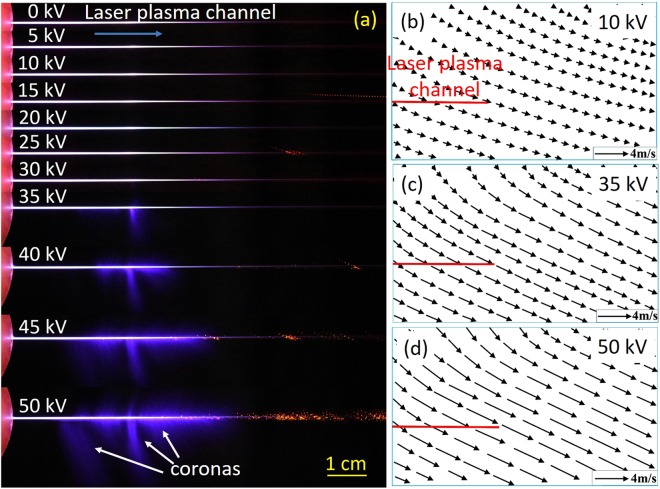
(a) Real-color images of discharges generated along the laser plasma channel in air with applied voltages ranging from 0 kV to 50 kV, and (b–d) the 2D flow fields of the ionic wind at the voltages of 10 kV, 35 kV, and 50 kV, respectively. Clear discharges guided by laser were assigned by the arrows. The recording parameters of the camera for (b–d) are S = 1/50 s, F = 4, and ISO = 25600 (b) S = 1/200 s, F = 4, and ISO = 25600 (c) S = 1/500 s, F = 4, and ISO = 25600 (d), respectively.

The maximum ionic wind velocity as a function of the applied voltage. Squared points are the measurement results and the red dashed and blue dashed dot line are the linear fits.
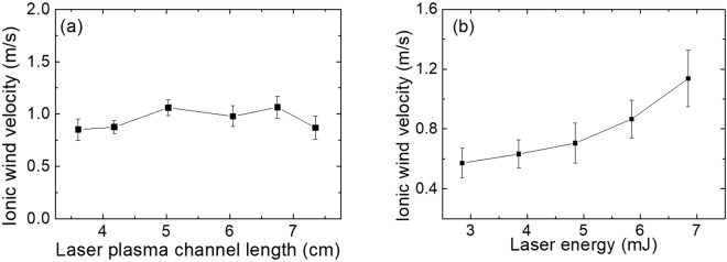
Measured ionic wind velocity as a function of (a) air plasma length outside the electrode and (b) the laser pulse energy. See more details in the text.
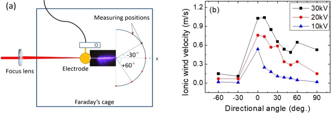
(a) The schematic of directional angle measurement of ionic wind. The electrode was held by an insulated plastic holder as shown in the figure. (b) The measured maximum ionic wind velocity as a function of detection angle. 1 kHz/25 fs/6.85 mJ femtosecond laser pulse was used to create plasma channel with a 50 cm focal length lens. The high voltage was fixed at 10 kV, 20 kV and 30 kV, respectively.
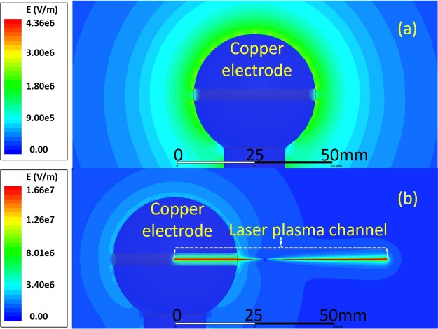
Electric field distribution around the spherical electrode when a high voltage of 50 kV was used (a) without laser plasma channel and (b) with laser plasma channel.
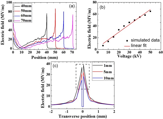
simulated electric field around the laser plasma channel end: (a) electric field distribution around the laser plasma channel end under different filament lengths of 40 mm, 50 mm, 60 mm, and 70 mm. The applied voltage was 50 kV; (b) the peak electric field around the end of 60 mm long plasma channel as a function of applied voltage. (c) the electric field distribution in the direction perpendicular to the laser propagation direction at three positions of 1 mm, 5 mm and 10 mm before the filament ends. The laser plasma channel position is defined as 0 and the negative transverse position is the side where the electrode was connected to the power supply (See Figs 1 and 5a).
References
-
- Robinson M. A history of the electric wind. American Journal of Physics. 1962;30:366–372. doi: 10.1119/1.1942021. - DOI
-
- Goldman M, Goldman A, Sigmond RS. The corona discharge, its properties and specific uses. Pure & Applied Chemistry. 1985;57:1353–1362. doi: 10.1351/pac198557091353. - DOI
-
- Moreau E. Airflow control by non-thermal plasma actuators. Journal of Physics D: Applied Physics. 2007;40:605–636. doi: 10.1088/0022-3727/40/3/S01. - DOI
-
- Rayman MD, Lehman DH. Deep Space One: NASA’s first deep-space technology validation mission. Acta Astronautica. 1997;41:289–299. doi: 10.1016/S0094-5765(98)00073-3. - DOI
-
- Rayman MD. The Deep Space 1 extended mission: challenges in preparing for an encounter with comet Borrelly. Acta Astronautica. 2002;51:507–516. doi: 10.1016/S0094-5765(02)00070-X. - DOI
LinkOut - more resources
Full Text Sources
Other Literature Sources
