

Enabling tomography with low-cost C-arm systems
- PMID: 30212543
- PMCID: PMC6136768
- DOI: 10.1371/journal.pone.0203817
Enabling tomography with low-cost C-arm systems
Abstract
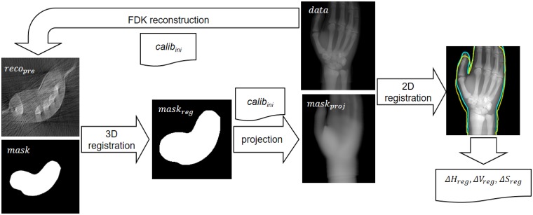
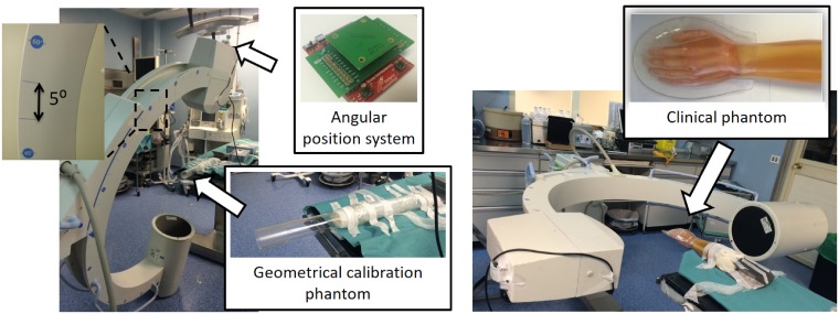
In scenarios where the use of a Computed Tomography (CT) is difficult, such as during surgery or in the ICU, the use of a C-arm system to generate tomographic information could contribute with interesting additional clinical information. Recent days are seeing the development of the so-called cone-beam CT (CBCT) based on advanced motorized isocentric C-arm systems. To be able to make use of more basic C-arm systems, apart from the geometric non-idealities common to any CBCT, we need to address other difficulties. First, the trajectory of the source-detector pair may differ from a circular path and the system may suffer mechanical strains that modify the relative positions of the source and detector for different projection angles. Second, and more importantly, the exact position of the source and detector elements may not be repeatable for consecutive rotations due to low mechanical precision, thus preventing an accurate geometrical calibration of the system. Finally, the limitation of the angular span and the difficulty of obtaining a high number of projections pose a great challenge to the image reconstruction. In this work, we present a novel method to adapt a standard C-arm, originally designed for planar imaging, to be used as a tomograph. The key parts of the new acquisition protocol are (1) a geometrical calibration method to compensate mechanical inaccuracies that prevent an accurate repetition of source-detector position between acquisitions, and (2) an advanced image reconstruction method able to deal with limited angle data, sparse projections and non-circular trajectories. Both methods exploit surface information from the patient, which can be obtained using a 3D surface scanner. The proposed method was evaluated with two real C-arm systems, based on an image intensifier and a flat panel detector respectively, showing the feasibility of the proposal.
Conflict of interest statement
The authors have declared that no competing interests exist.
Figures


References
-
- Amiri S, Wilson DR, Masri BA, Anglin C. A low-cost tracked C-arm (TC-arm) upgrade system for versatile quantitative intraoperative imaging. Int J CARS. 2014; 9(4): 695–711. - PubMed
-
- Siewerdsen JH, Daly MJ, Bachar G, Moseley DJ, Bootsma G, Brock KK, et al. Multi-Mode C-Arm Fluoroscopy, Tomosynthesis, and Cone-Beam CT for Image-Guided Interventions: From Proof of Principle to Patient Protocols. Proc SPIE. 2007; 6510: 434–44.
-
- Purdie TG, Bissonnette JP, Franks K, Bezjak A, Payne D, Sie F, et al. Cone-beam computed tomography for on-line image guidance of lung stereotactic radiotherapy: Localization, verification, and intrafraction tumor position. Int J Radiat Oncol Biol Phys. 2007; 68(1): 243–52. 10.1016/j.ijrobp.2006.12.022 - DOI - PubMed
-
- White EA, Cho J, Vallis KA, Sharpe MB, Lee G, Blackburn H, et al. Cone beam computed tomography guidance for setup of patients receiving accelerated partial breast irradiation. Int J Radiat Oncol Biol Phys. 2006; 68(2): 547–54. - PubMed
Publication types
MeSH terms
LinkOut - more resources
Full Text Sources
Other Literature Sources
