Review
. 2018 Sep 13;11(9):1716.
doi: 10.3390/ma11091716.

Biomedical Porous Shape Memory Alloys for Hard-Tissue Replacement Materials

Affiliations
Review

Biomedical Porous Shape Memory Alloys for Hard-Tissue Replacement Materials

Bin Yuan et al. Materials (Basel). .

Abstract

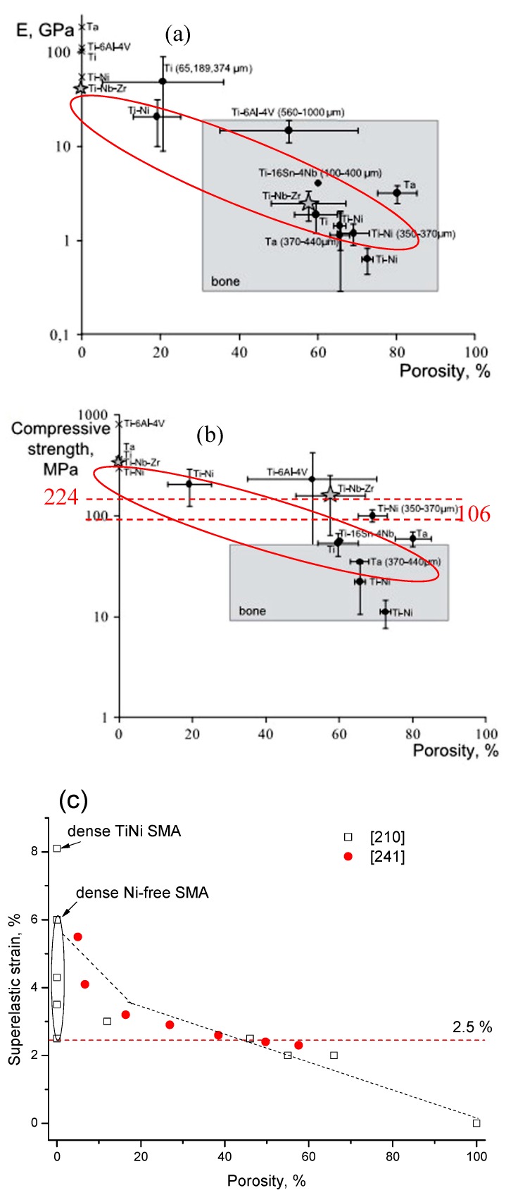
Porous shape memory alloys (SMAs), including NiTi and Ni-free Ti-based alloys, are unusual materials for hard-tissue replacements because of their unique superelasticity (SE), good biocompatibility, and low elastic modulus. However, the Ni ion releasing for porous NiTi SMAs in physiological conditions and relatively low SE for porous Ni-free SMAs have delayed their clinic applications as implantable materials. The present article reviews recent research progresses on porous NiTi and Ni-free SMAs for hard-tissue replacements, focusing on two specific topics: (i) synthesis of porous SMAs with optimal porous structure, microstructure, mechanical, and biological properties; and, (ii) surface modifications that are designed to create bio-inert or bio-active surfaces with low Ni releasing and high biocompatibility for porous NiTi SMAs. With the advances of preparation technique, the porous SMAs can be tailored to satisfied porous structure with porosity ranging from 30% to 85% and different pore sizes. In addition, they can exhibit an elastic modulus of 0.4⁻15 GPa and SE of more than 2.5%, as well as good cell and tissue biocompatibility. As a result, porous SMAs had already been used in maxillofacial repairing, teeth root replacement, and cervical and lumbar vertebral implantation. Based on current research progresses, possible future directions are discussed for "property-pore structure" relationship and surface modification investigations, which could lead to optimized porous biomedical SMAs. We believe that porous SMAs with optimal porous structure and a bioactive surface layer are the most competitive candidate for short-term and long-term hard-tissue replacement materials.

Keywords: NiTi; biocompatibility; porous material; shape memory alloy; surface modification; β type Ni-free Ti alloy.


Conflict of interest statement

The authors declare no conflict of interest.

Figures

Figure 1
Figure 1
The stress-strain curves for dense NiTi shape memory alloys (SMAs), stainless steel, bone, and tendon [6].
Figure 2
Figure 2
Schematic determination of MT temperature in a NiTi SMA via a differential scanning calorimetry (DSC) plot [19].
Figure 3
Figure 3
Two-dimensional (2D) crystallographic mechanism of SME (V1 represents one martensite variant, V2 represents another variant).
Figure 4
Figure 4
Stress-strain curve of superelasticity (SE) in an SMA (ab—elastic deformation of austenite, bc—forming martensite by stress induced martensitic transformation (SIMT), cd—elastic deformation of martensite, de-recovery of elastic deformation of martensite, ef—austenite forming by reverse MT, fg—recovery of elastic deformation of austenite).
Figure 5
Figure 5
Microstructure illustration of human hard-tissue: (a) human bone [23] and (b) human tooth [34] (magnification image is SEM of actual tissue in a specific region).
Figure 6
Figure 6
Homogeneous pore structure in porous NiTi SMAs by various methods: (a) CS [12]; (b) SHS [57]; (c) thermal explosion mode in high temperature synthesis (SHS) [12]; (d) capsule-free hot isostatic pressing (CF-HIP) [12]; (e) SLM (the inset image is the designed part corresponding to the fabricated one) [63]; and, (f) SLM (the inset image is a macrograph) [64].
Figure 7
Figure 7
Inhomogeneous pore structure in porous NiTi SMAs: “sandwich-like” structure (a), radial gradient structure (b) by CF-HIP [84], radial gradient structure (c) and axial gradient structure (d) by low pressing sintering.
Figure 8
Figure 8
Schematic illustration in the filling of the powder mixture for fabricating two gradient porosity NiTi SMAs (Ti-1 or Ti-2 represents one Ti powder with a certain particle size, the same meaning for the Ni-1 or Ni-2).
Figure 9
Figure 9
Microstructure of porous NiTi SMAs by: (a) conventional sintering (CS) with Ni/Ti powders at 1100 °C for 2 h; (b) CS with Ni/TiH2 powders at 1100 °C for 2 h [86]; (c) CF-HIP, 1050 °C for 3 h [54]; and, (d) SHS and post-reaction heat treatment at 1150 °C for 1 h [58].
Figure 10
Figure 10
Schematic model of microstructural evolution during reactive sintering and furnace cooling: (ad) Ni/Ti; (eh) Ni/TiH2. Region <942 °C is the solid-state reaction process. Dehydrogenation and separation of newly born Ti powders are shown in (f); Region >942 °C is the LPS; Region cooling is final structure below 620 °C after furnace cooling. White lines and black dots indicate the needle-like Ni3Ti and spherical NiTi2 eutectoid precipitates formed during cooling. [86].
Figure 11
Figure 11
DSC heating (a) and cooling (b) curves of porous NiTi SMAs fabricated by three methods (CS, SHS, and CF-HIP) [66].
Figure 12
Figure 12
Martensitic transformation temperature dependence of porosity for porous NiTi SMAs with different compositions: (a) Ni50.8Ti49.2 [54,66]; and, (b) Ni49Ti51 [76].
Figure 13
Figure 13
Compressive stress-strain curves: (a) homogeneous porous NiTi SMAs by CF-HIP with different porosities at RT; and, (b) gradient porosity of 20–61% [74].
Figure 14
Figure 14
Compressive load–unload recovery cycles under the compressive stress of porous NiTi SMAs by CS with 15% (a) and 28% (b) porosity [86].
Figure 15
Figure 15
Superelastic behavior of the porous SMAs: (a) elastic modulus for the samples with a porosity of 0.1, 0.2, and 0.4; (b) macroscopic critical SIM stress for the onset of transformation as a function of porosity; and, (c) average stress–strain responses for the samples with porosity. [90].
Figure 16
Figure 16
The relationship between elastic modulus (a), compressive stress at 3% strain (b), maximum superelastic strain (c) and porosity for porous NiTi (Ti49.2Ni50.8) SMAs prepared by various methods (data from refs. [160,161,162] are Ti49.4Ni50.6).
Figure 16
Figure 16
The relationship between elastic modulus (a), compressive stress at 3% strain (b), maximum superelastic strain (c) and porosity for porous NiTi (Ti49.2Ni50.8) SMAs prepared by various methods (data from refs. [160,161,162] are Ti49.4Ni50.6).
Figure 17
Figure 17
The S-N curves for porous NiTi SMAs with different porosities in terms of (a) the yield value and (b) the maximum applied stress [105].
Figure 17
Figure 17
The S-N curves for porous NiTi SMAs with different porosities in terms of (a) the yield value and (b) the maximum applied stress [105].
Figure 18
Figure 18
Loading-unloading curves for a sintered porous NiTi implant (Φ4 × 4 mm3 cylinders) deformed in compression mode before implantation (curve 2), after one month (curve 3) and after three months (curve 1) of implantation in rabbits [110].
Figure 19
Figure 19
Extracted electrochemical parameters from polarization curves in a 0.9% NaCl solution for 24 h with porosity in porous NiTi SMAs [110].
Figure 20
Figure 20
Ni ion releasing content of porous NiTi SMAs by CF-HIP with different pore sizes dependence of immersion duration (the safety line represents for the acceptable Ni ion content to the human body 0.5 μm/cm2/week [111]).
Figure 21
Figure 21
Ni leaching level of porous NiTi treated by different wet chemical treatments (a), in comparison with untreated NiTi and safety Ni level to human body; (b) is an enlarged area from (a). (PA: passivation in HNO3; O-PIII: Oxygen PIII; NaOH-treated: treated in NaOH solution) [111].
Figure 22
Figure 22
Optical image (a) and SEM image (b) of porous NiTi SMAs fabricated by sintering and in-situ nitriding (inset image in (a) is a macrographic image) [165].
Figure 23
Figure 23
In vitro cell attachment (a) and in vivo Ni leaching (b) porous NiTi SMAs treated by in situ nitriding comparing with untreated porous NiTi [165].
Figure 24
Figure 24
Biomedical products made by porous NiTi SMAs: (a) Cervical spine implantation [169]; (b) lumbar spine implantation [169]; (c) intervertebral fusion device [169]; (d) acetabular cup [167]; (e) tooth [170]; and, (f) gum tissue replacement [167].
Figure 24
Figure 24
Biomedical products made by porous NiTi SMAs: (a) Cervical spine implantation [169]; (b) lumbar spine implantation [169]; (c) intervertebral fusion device [169]; (d) acetabular cup [167]; (e) tooth [170]; and, (f) gum tissue replacement [167].
Figure 25
Figure 25
DSC curves of the sintered Ti-(8–18) at.% Nb alloys (0.8 wt.% oxygen in the alloys) [194].
Figure 26
Figure 26
The effect of Nb on Ms (a) for Ti-Nb binary alloys and alloy elements on Ms (b) for Ti-Nb-based ternary alloys [172].
Figure 27
Figure 27
The stress-strain curves obtained by tensile test for Ti-19Nb-9Zr SMAs: (a) cyclic loading-unloading; (b) after five cycles of loading-unloading tests [209].
Figure 28
Figure 28
Compressive stress-strain curves of Ti-11Nb and Ti-22Nb alloys (a), and constant strain (pre-strain = 5%) cycling curves (b) of Ti-11Nb after solution treatment at RT [212].
Figure 29
Figure 29
Extended phase stability index diagram based on Bo¯ and Md¯ parameters in which about 80 shape memory and low elastic Ti alloys. The shadow zone indicates the coexistence of both properties [216].
Figure 30
Figure 30
Mechanical properties of Ti-based SMAs, in comparison with other materials: (a) tension strength vs. elongation [217]; and, (b) yield strength v.s. young’s modulus.
Figure 30
Figure 30
Mechanical properties of Ti-based SMAs, in comparison with other materials: (a) tension strength vs. elongation [217]; and, (b) yield strength v.s. young’s modulus.
Figure 31
Figure 31
Fatigue properties of Ti-Nb-Ta-Zr alloys subjected to aging treatment at 573 K for 10.8 ks (AT10.8), solution treatment (ST), and severe cold rolling (CR) [223].
Figure 32
Figure 32
Attached number of living-MG63 cells (a) and cell proliferation index (b) as a function of the incubation time. The groups marked with the same symbol have no statistically significant differences at different times of culture [230].
Figure 33
Figure 33
Histotomy of bone contact of the Ti–Nb alloy (a,c) and Ti (b,d) at 4 weeks and 12 weeks illustrated by fluorescence-dyeing reagents, respectively. Green (#) revealed the new bone formation of two-week duration dyed by calcein, and the yellow (Δ) revealed that new formation of four-week duration by tetracycline [231].
Figure 34
Figure 34
Oxygen, carbon, nitrogen, and hydrogen contents in bulk, powder and porous Ti-Nb-Zr specimens [210] (Inset contains maximum concentrations according to ASTM F67-00).
Figure 35
Figure 35
Pore morphology of porous Ti-22Nb-6Zr SMA with various porosities by different methods: (a) 6.7% by CS [241]; (b) 12% by CF-HIP [234]; (c) 57.6% by CS with NH4HCO3 [241]; and, (d) 65% by CS with pore forming agent from alloy powder [217].
Figure 36
Figure 36
Porous Ti-25 wt.% Nb alloys with 70% porosity fabricated by PM using polyurethane as space holder [243]: (a) macrographic image, and (b) pore structure.
Figure 37
Figure 37
(a) The morphology of the electron beam melting (EBM)-produced porous Ti-24Nb-4Zr-8Sn (wt.%) SMAs; (b) the single unit of 3D rhombic dodecahedron modeling; and, (c) the surface morphology [239].
Figure 38
Figure 38
Compressive stress-strain curves of porous Ti-Nb-Zr alloys and cortical bone [210].
Figure 39
Figure 39
Stress-strain cycle curves for porous Ti-21Nb-5.5Zr alloys under various testing modes at RT: (a) compressive; (b) tensile; and, (c) bending [210].
Figure 40
Figure 40
The relationship between elastic modulus (a); compressive strength; (b) [210]; and, superelastic strain (c) [210,217,241] and porosity for Ni-free SMAs.
Figure 41
Figure 41
(a) The normalized S-N curves of the porous Ti2448 and Ti-6Al-4V alloys with different porosities, and (b) the relationship of Young’s modulus and the fatigue strength for the porous Ti2448 and Ti-6Al-4V specimens [239].
Figure 42
Figure 42
Confocal micrographs of cell growth: (a) inside pores and (b) on the surface of the porous TiNbZr alloys [14].
Figure 43
Figure 43
Biomedical applications made by porous Ni-free SMAs: (a) spine implantations [167]; and, (b) spine complete replacements [263].

Similar articles

Cited by

References

    1. World Population Prospects 2017. Population Division, DESA, United Nations; New York, NY, USA: 2017.
    1. Gage B.F., Birman-Deych E., Radford M.J., Nilasena D.S., Binder E.F. Risk of osteoporotic fracture in elderly patients taking warfarin: Results from the National Registry of Atrial Fibrillation. Arch. Intern. Med. 2006;166:241–246. doi: 10.1001/archinte.166.2.241. - DOI - PubMed
    1. Wise D.L. Biomaterials Engineering and Devices. Humana Press; Berlin, Germany: 2000. pp. 205–319.
    1. Park J.B., Bronzino J.D. Biomaterials: Principles and Applications. CRC Press; Boca Rator, FL, USA: 2003. pp. 1–241.
    1. Geetha M., Singh A.K., Asokamani R., Gogia A.K. Ti based biomaterials, the ultimate choice for orthopaedic implants–A review. Prog. Mater. Sci. 2009;54:397–425. doi: 10.1016/j.pmatsci.2008.06.004. - DOI

LinkOut - more resources