. 2018 Aug;474(2216):20170705.
doi: 10.1098/rspa.2017.0705. Epub 2018 Aug 8.

Interfacial load transfer mechanisms in carbon nanotube-polymer nanocomposites

Affiliations

Interfacial load transfer mechanisms in carbon nanotube-polymer nanocomposites

Soumendu Bagchi et al. Proc Math Phys Eng Sci. 2018 Aug.

Abstract

Carbon nanotubes (CNTs) are highly promising for strength reinforcement in polymer nanocomposites, but conflicting interfacial properties have been reported by single nanotube pull-out experiments. Here, we report the interfacial load transfer mechanisms during pull-out of CNTs from PMMA matrices, using massively- parallel molecular dynamics simulations. We show that the pull-out forces associated with non-bonded interactions between CNT and PMMA are generally small, and are weakly-dependent on the embedment length of the nanotube. These pull-out forces do not significantly increase with the presence of Stone Wales or vacancy defects along the nanotube. In contrast, low-density distribution of cross-links along the CNT-PMMA interface increases the pull-out forces by an order of magnitude. At each cross-linked site, mechanical unfolding and pull-out of single or pair polymer chain(s) attached to the individual cross-link bonds result in substantial interfacial strengthening and toughening, while contributing to interfacial slip between CNT and PMMA. Our interfacial shear-slip model shows that the interfacial loads are evenly-distributed among the finite number of cross-link bonds at low cross-link densities or for nanotubes with short embedment lengths. At higher cross-link densities or for nanotubes with longer embedment lengths, a no-slip zone now develops where shear-lag effects become important. Implications of these results, in the context of recent nanotube pull-out experiments, are discussed.

Keywords: carbon nanotubes; cross-link bonds; molecular dynamics; polymer nanocomposites; shear-slip.


Conflict of interest statement

We have no competing interests.

Figures

Figure 1.
Figure 1.
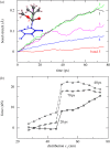
Model structure of the CNT-PMMA composite. (a) Schematic of the pull-out of a CNT embedded within a PMMA matrix subjected to applied force (Fx). (b) Close-up view of three monomer units of a PMMA polymer chain, with C, H, and O atoms coloured in grey, pink, and red, respectively. (c) Atomic configurations of a SWCNT (blue) with embedment length of L = 500 nm in a PMMA matrix (grey) at the initial stage and the ends of stages I to IV. (d) Evolution of PMMA density through stages I to IV. (Online version in colour.)
Figure 2.
Figure 2.
Pull-out of pristine SWCNT from PMMA matrix with initial embedment lengths (L) of 100 nm (a,b) and 500 nm (c,d). Above: displacements of the front and back ends of the SWCNT with increasing pull-out force (Fx). Below: cross-sectional views of SWCNTs during the pull-out process. (Online version in colour.)
Figure 3.
Figure 3.
Effects of non-bonded interactions on the critical pull-out forces (Fc) for (a) pristine SWCNTs of varying embedment lengths (L), and (b,c) SWCNTs with varying proportions of Stone–Wales (b) and vacancy (c) defect densities. (Online version in colour.)
Figure 4.
Figure 4.
Pull-out of a SWCNT embedded within a PMMA matrix, subjected to Fx = 16 nN, with a single cross-link located near the middle of the L = 100 nm embedment length of the SWCNT. (a) Stretching of the various covalent bonds in the vicinity of the cross-link (bond 1), as defined by the atomic configuration in the inset; C, H, and O atoms representing the cross-linked polymer chain are coloured in grey, pink, and red, while C atoms and associated C─C bonds within the SWCNT are coloured in blue. (b) Axial force distributions along the embedment length of the SWCNT at three time instances. (Online version in colour.)
Figure 5.
Figure 5.
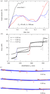
Pull-out of SWCNT from PMMA matrix, with three cross-linked bonds located along the L = 300 nm embedment length, subjected to Fx = 30 nN. (a) Bond stretch of the individual cross-links over time. (b) Axial force distributions along the embedment length of the SWCNT at three time instances. (c) Close-up view of the atomic configurations at three time instances, filtered to display only the SWCNT and the cross-linked PMMA chains. (Online version in colour.)
Figure 6.
Figure 6.
Pull-out of SWCNT from PMMA matrix, with five cross-linked bonds located along the L = 300 nm embedment length, subjected to Fx = 40 nN. (a) Bond stretch of the individual cross-links over time. (b) Axial force distributions along the embedment length of the SWCNT at three time instances. (c) Close-up view of the atomic configurations at three time instances, filtered to display only the SWCNT and the cross-linked PMMA chains. (Online version in colour.)
Figure 7.
Figure 7.
(a) Steady-state axial force distributions along three SWCNTs of L = 500 nm embedment length: (i) five cross-links with Fx = 40 nN, (ii) five cross-links with Fx = 50 nN, and (iii) nine cross-links with Fx = 50 nN. Solid and dashed lines denote results from MD simulations and analytical interfacial shear-slip model predictions, respectively. (b) Axial stress contours within the PMMA matrix for the configurations in (a), with locations of the cross-links as marked. (c,d) Stress–strain response of bulk PMMA under uniaxial tensile deformation (c), and associated atomic configurations (d). (Online version in colour.)
Figure 8.
Figure 8.
Interfacial shear-slip model. (a) Schematic of a three-phase shear-lag model accounting for slip along the CNT-PMMA interface. (b) Applied pull-out force (Fb) versus slip length (δs) for a cross-link attached to the middle (M) or the unterminated end (E) of a PMMA chain. (c,d) Close-up views of the atomic configurations of the polymer chains attached to the (M)- and (E)-type cross-links, respectively, at various slip-lengths; configurations are filtered to display only the SWCNT and the single polymer chain attached to the cross-linked bond. (Online version in colour.)
Figure 9.
Figure 9.
Effects of bond-spacings (bs) on the axial force (a,b) and shear stress (c,d) distributions along a SWCNT of embedment length L = 800 nm with mid-chain (M) and end-chain (E) bonded cross-links, subjected to Fx = 50 nN. Open symbols in (c,d) denote the transition from interfacial slip (right) to shear-lag behaviour (left).
Figure 10.
Figure 10.
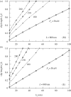
Effects of applied pull-out force (Fx) and bond spacing (bs) on the slip-length (Ls) along a SWCNT of embedment length L = 800 nm with (a) mid-chain (M) and (b) end-chain (E) bonded cross-links.
Figure 11.
Figure 11.
(a,b) Critical pull-out force (Fc) versus bond spacing (bs) for mid-chain (M) and end-chain (E) bonded cross-links along nanotubes of varying embedment lengths (L). (c) Comparison of model predictions for nanotubes with assumed (M)-type cross-link bonds versus experimental pull-out data [2]. (d) Fracture toughness (Jc) along nanotube-PMMA interface versus bond spacing (bs) for both (M)- and (E)-type cross-links, as denoted by solid curves; slip contribution to Jc denoted by dashed curves. (Online version in colour.)

References

    1. Zhang S, Mielke SL, Khare R, Troya D, Ruoff RS, Schatz GC, Belytschko T. 2005. Mechanics of defects in carbon nanotubes: atomistic and multiscale simulations. Phys. Rev. B 71, 115403 (10.1103/PhysRevB.71.115403) - DOI
    1. Chen XM, Zheng M, Park C, Ke CH. 2013. Direct measurements of the mechanical strength of carbon nanotube-poly(methyl methacrylate) interfaces. Small 9, 3345–3351. (10.1002/smll.201202771) - DOI - PubMed
    1. Tsuda T, Ogasawara T, Deng F, Takeda N. 2011. Direct measurements of interfacial shear strength of multi-walled carbon nanotube/PEEK composite using a nano-pullout method. Compos. Sci. Technol. 71, 1295–1300. (10.1016/j.compscitech.2011.04.014) - DOI
    1. Ganesan Y, et al. 2011. Interface toughness of carbon nanotube reinforced epoxy composites. ACS Appl. Mater. Interfaces. 3, 129–134. (10.1021/am1011047) - DOI - PubMed
    1. Ding W, Calabri L, Kohlhaas KM, Chen X, Dikin DA, Ruoff RS. 2007. Modulus, fracture strength, and brittle vs. plastic response of the outer shell of arc-grown multi-walled carbon nanotubes. Exp. Mech. 47, 25–36. (10.1007/s11340-006-9344-6) - DOI

LinkOut - more resources