. 2018 Nov;45(11):5066-5079.
doi: 10.1002/mp.13190. Epub 2018 Oct 17.

A novel real-time computational framework for detecting catheters and rigid guidewires in cardiac catheterization procedures

Affiliations

A novel real-time computational framework for detecting catheters and rigid guidewires in cardiac catheterization procedures

YingLiang Ma et al. Med Phys. 2018 Nov.

Abstract

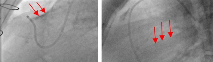
Purpose: Catheters and guidewires are used extensively in cardiac catheterization procedures such as heart arrhythmia treatment (ablation), angioplasty, and congenital heart disease treatment. Detecting their positions in fluoroscopic X-ray images is important for several clinical applications, for example, motion compensation, coregistration between 2D and 3D imaging modalities, and 3D object reconstruction.

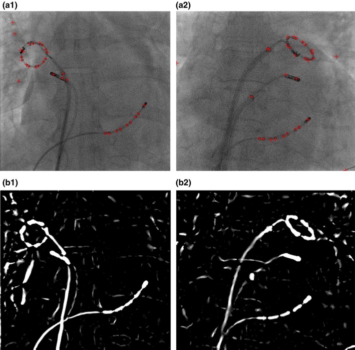
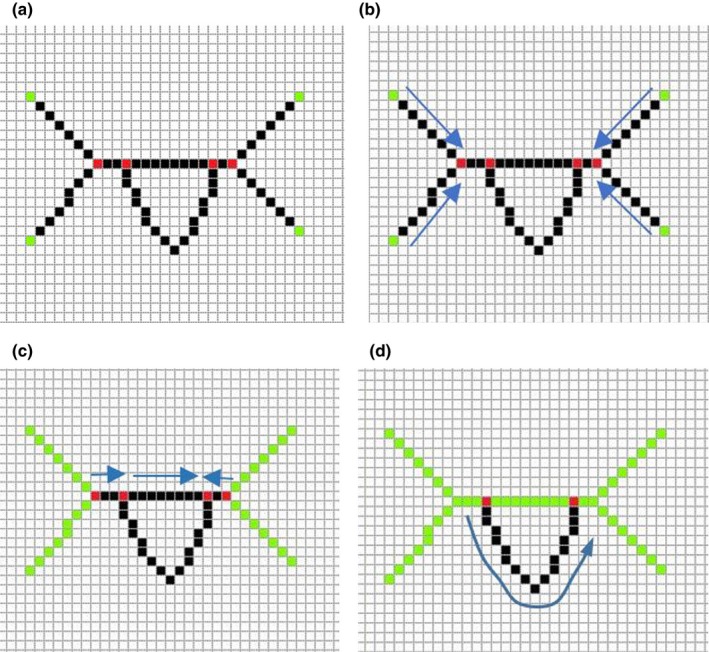
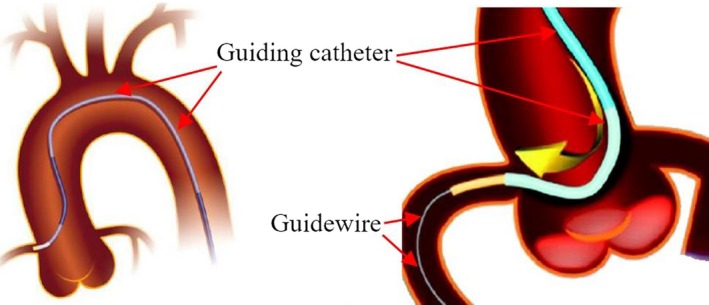
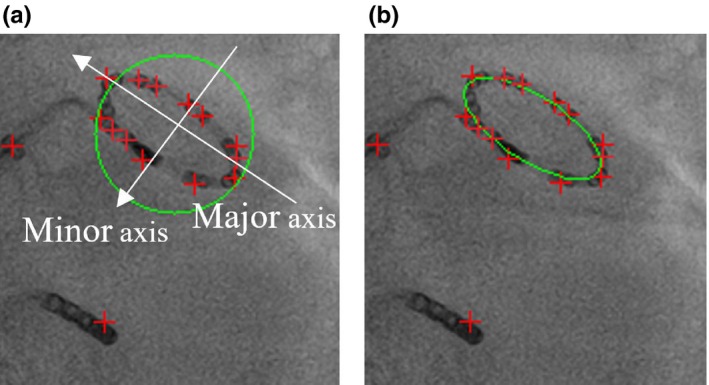
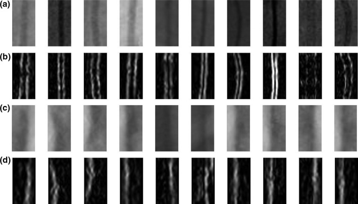
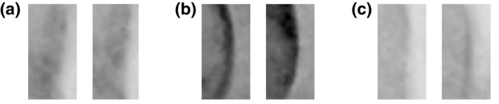
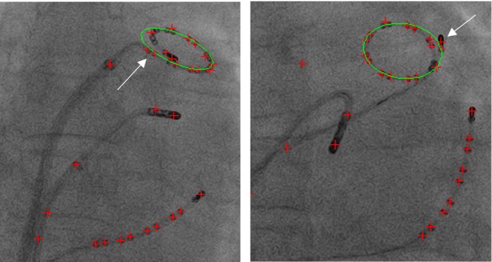
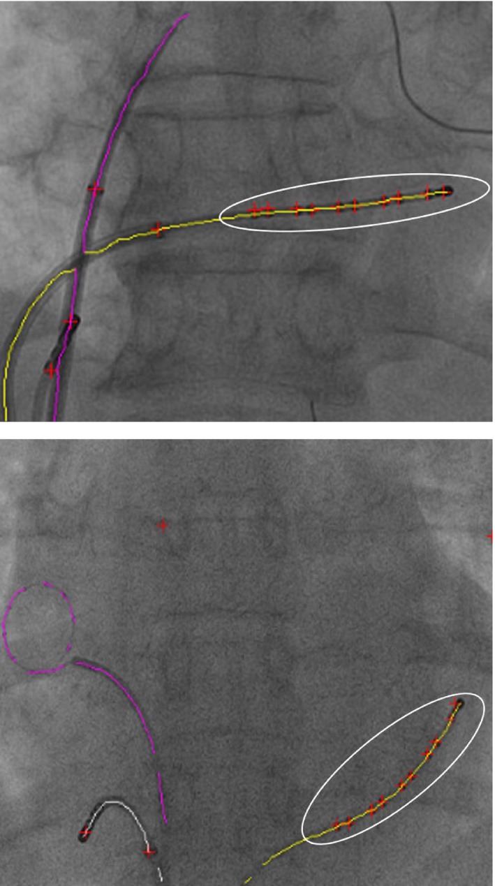
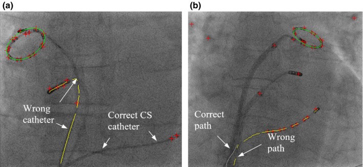
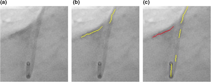
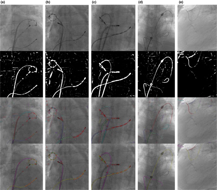
Methods: For the generalized framework, a multiscale vessel enhancement filter is first used to enhance the visibility of wire-like structures in the X-ray images. After applying adaptive binarization method, the centerlines of wire-like objects were extracted. Finally, the catheters and guidewires were detected as a smooth path which is reconstructed from centerlines of target wire-like objects. In order to classify electrode catheters which are mainly used in electrophysiology procedures, additional steps were proposed. First, a blob detection method, which is embedded in vessel enhancement filter with no additional computational cost, localizes electrode positions on catheters. Then the type of electrode catheters can be recognized by detecting the number of electrodes and also the shape created by a series of electrodes. Furthermore, for detecting guiding catheters or guidewires, a localized machine learning algorithm is added into the framework to distinguish between target wire objects and other wire-like artifacts. The proposed framework were tested on total 10,624 images which are from 102 image sequences acquired from 63 clinical cases.

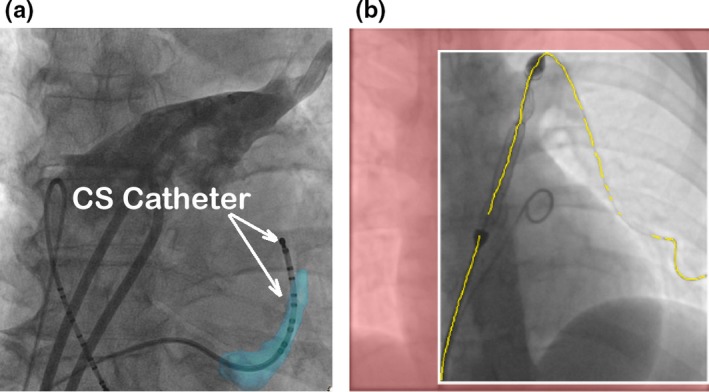
Results: Detection errors for the coronary sinus (CS) catheter, lasso catheter ring and lasso catheter body are 0.56 ± 0.28 mm, 0.64 ± 0.36 mm, and 0.66 ± 0.32 mm, respectively, as well as success rates of 91.4%, 86.3%, and 84.8% were achieved. Detection errors for guidewires and guiding catheters are 0.62 ± 0.48 mm and success rates are 83.5%.

Conclusion: The proposed computational framework do not require any user interaction or prior models and it can detect multiple catheters or guidewires simultaneously and in real-time. The accuracy of the proposed framework is sub-mm and the methods are robust toward low-dose X-ray fluoroscopic images, which are mainly used during procedures to maintain low radiation dose.

Keywords: cardiac catheterization procedures; catheter detection; electrophysiology; guidewire detection.


Figures

Figure 1
Figure 1
(a) Aligning the CS model (light blue color) with the CS catheter in the X‐ray image for 2D to 3D registration. (b) Localized guidewires are shown in yellow. The predicted collimation box is shown with white boundaries with the area outside set to red. [Color figure can be viewed at http://www.wileyonlinelibrary.com]
Figure 2
Figure 2
Outputs from vessel enhancement filter. (a) Blob positions (red crosses). (b) Enhanced wire‐like objects. [Color figure can be viewed at http://www.wileyonlinelibrary.com]
Figure 3
Figure 3
(a) Step one: find the branch and end points. The red points are branch points and green points are end points. (b) Step two: extract segments from one end point to the nearest branch point along the skeleton. (c) Step three: extract segments from one branch point to the nearest branch point along the skeleton. Green line segments are extracted segments. (d) Step four: Detect any unused image pixels within the skeleton. If unused pixels are found, extract line segments from the nearest branch point to another one. [Color figure can be viewed at http://www.wileyonlinelibrary.com]
Figure 4
Figure 4
(a) Guiding Catheter. (b) Guiding catheter and guidewire. [Color figure can be viewed at http://www.wileyonlinelibrary.com]
Figure 5
Figure 5
End point and tangent vector definitions for the cost function. [Color figure can be viewed at http://www.wileyonlinelibrary.com]
Figure 6
Figure 6
Illustration for local curvature approximation. [Color figure can be viewed at http://www.wileyonlinelibrary.com]
Figure 7
Figure 7
con_dist and dev_dist distance definitions. [Color figure can be viewed at http://www.wileyonlinelibrary.com]
Figure 8
Figure 8
Lasso catheter ring. Electrodes are overlapped in the areas indicated by arrows. [Color figure can be viewed at http://www.wileyonlinelibrary.com]
Figure 9
Figure 9
(a) Estimated enclosing circle. (b) Final detected lasso catheter ring. [Color figure can be viewed at http://www.wileyonlinelibrary.com]
Figure 10
Figure 10
Image artifacts (indicated by red arrows) in X‐ray images. [Color figure can be viewed at http://www.wileyonlinelibrary.com]
Figure 11
Figure 11
Training samples for KNN. (a) Positive data including guiding catheters and guidewires. (b) Positive data after applying Sobel filter and normalization. (c) Negative data such as calcium deposit and rib bones. (d) Negative data after applying Sobel filter and normalization.
Figure 12
Figure 12
Failed classifications for negative data (artifacts were classified as wire objects). (a) Intersection with a catheter. (b) X‐ray contrast agent injection. (c) Calcium deposit.
Figure 13
Figure 13
Two examples of failed lasso ring detection (some areas have large errors). Green ellipse is the detected lasso ring. Red crosses are detected blob positions. Both have the large deviation of the fitted ellipse, which is distracted by the blobs nearby (either by the catheter tip electrode or last few electrodes on the lasso catheter). [Color figure can be viewed at http://www.wileyonlinelibrary.com]
Figure 14
Figure 14
Two examples of successful CS catheter detection. The white ellipse highlights the selected group of blobs on the detected CS catheter. Red crosses are detected blobs. [Color figure can be viewed at http://www.wileyonlinelibrary.com]
Figure 15
Figure 15
Two examples of failed CS catheter detection. Yellow lines are detected CS catheters. Red crosses are detected blob positions. (a) Failure due to the detected wrong catheter. (b) Failure due to overlapping catheters near the image edge. There are small deviations of the fitted ellipses because of the nearby catheter tip electrode. [Color figure can be viewed at http://www.wileyonlinelibrary.com]
Figure 16
Figure 16
(a) Original image. (b) The wire path reconstruction distracted by image artifacts. (c) The correct wire path (yellow lines). The detected image artifacts (red lines). [Color figure can be viewed at http://www.wileyonlinelibrary.com]
Figure 17
Figure 17
Detection workflow. From top to bottom, the first row are original images. The second row are images after applying vessel filter. The third row are results of centreline extraction and segmentation. The bottom row are final detection results. The figures are best viewed in color. (a) (b) (c) CS and lasso catheter detection. In the final result image, the yellow line is CS catheter, the green circle or ellipse is lasso catheter ring and the purple line is lasso catheter body. Red crosses are the locations of blobs. (d) Guidewire detection. The yellow and purple line are two guidewires. (e) Guiding catheter detection. The yellow line is the guiding catheter. The purple line is the other wire object. The red line is the image artifacts (calcium deposit). [Color figure can be viewed at http://www.wileyonlinelibrary.com]

References

    1. Ector J, De Buck S, Huybrechts W, et al. Biplane three‐dimensional augmented fluoroscopy as single navigation tool for ablation of atrial fibrillation: accuracy and clinical value. Heart Rhythm. 2008;5:957–964. - PubMed
    1. Knecht S, Skali H, O'Neill MD, et al. Computed tomography‐fluoroscopy overlay evaluation during catheter ablation of left atrial arrhythmia. Europace. 2008;10:931–938. - PubMed
    1. Sra J, Narayan G, Krum D, et al. Computed tomography‐fluoroscopy image integration‐guided catheter ablation of atrial fibrillation. J Cardiovasc Electrophysiol. 2007;18:409–414. - PubMed
    1. Rhode KS, Sermesant M, Brogan D, et al. A system for real‐time XMR guided cardiovascular intervention. IEEE Trans Med Imaging. 2005;24:1428–1440. - PubMed
    1. Mountney P, Behar JM, Toth D, et al. A planning and guidance platform for cardiac resynchronization therapy. IEEE Trans Med Imaging. 2017;36:2366–2375. - PubMed