

Review
doi: 10.1021/acs.chemrev.7b00767.
Epub 2018 Sep 17.
Switchable Fluorophores for Single-Molecule Localization Microscopy
- PMID: 30221931
- PMCID: PMC6476321
- DOI: 10.1021/acs.chemrev.7b00767
Item in Clipboard
Review
Switchable Fluorophores for Single-Molecule Localization Microscopy
Chem Rev.
.
Abstract
The past decade has witnessed an explosion in the use of super-resolution fluorescence microscopy methods in biology and other fields. Single-molecule localization microscopy (SMLM) is one of the most widespread of these methods and owes its success in large part to the ability to control the on-off state of fluorophores through various chemical, photochemical, or binding-unbinding mechanisms. We provide here a comprehensive overview of switchable fluorophores in SMLM including a detailed review of all major classes of SMLM fluorophores, and we also address strategies for labeling specimens, considerations for multichannel and live-cell imaging, potential pitfalls, and areas for future development.
Figures

Basic principle of SMLM. Scale bar indicates the ~250 nm diffraction limit of visible light.

On-off photoswitching of YFP. A single YFP molecule was illuminated with 488 nm light prior to odd-numbered frames, creating a nonfluorescent state. Illumination of nonfluorescent YFP with 405 nm light prior to even-numbered frames returned the molecule to the fluorescent state. The process could be repeated many times. Adapted by permission from Springer Customer Service Centre GmbH: Springer Nature, Ref. , Copyright 1997.
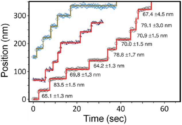
Trajectories of the motor protein Myosin V translocating along immobilized actin filaments, where the abrupt vertical jumps indicate individual stepping events. This was achieved by labeling Myosin V dimers on one head with a Cy3 fluorophore and then localizing the fluorophores to within a few nm uncertainty. From Ref. , adapted with permission from AAAS.

Impact of density of localizations on resolution achievable by SMLM. A high density of localizations (top row) resolves even the finest details on all of the test grids, while lower densities of localizations (middle and bottom rows) only resolves details about the larger grids. Reproduced by permission from Springer Customer Service Centre GmbH: Springer Nature, Ref. , Copyright 2008.

A) Simplified analysis of reversible switching, B) irreversible activation, and C) estimate of duty cycle, where koff is the rate of switching off, kon is the rate of switching on, koff,2 is the rate of bleaching for a reversible switch, DC is the duty cycle, ton is the average time spent in the on state prior to bleaching, and toff is the average time spent in the off state. Notably, DC is approximately the ratio of the on and off rates for both reversible switching and irreversible activation.

Comparison of photoswitching properties of three different fluorophores. A) Single-molecule on-off photoswitching of a representative Alexa Fluor 647 molecule in a deoxygenated solution containing a thiol. Under these conditions, Alexa Fluor 647 exhibits B) an average duty cycle of ~0.0012 and C) an average of ~5200 photons/localization. These switching properties are sufficient to produce high-quality images of hollow clathrin-coated pits in fixed, immunolabeled cells D-F). The fluorophore ATTO 655 has the same duty cycle as Alexa Fluor 647 G-H) but emits ~8× fewer photons per burst I), and the resulting larger position uncertainty obscures the hollow clathrin-coated pits J-L). The fluorophore Cy5.5 has a duty cycle that is ~6× larger that of Alexa Fluor 647 M-N), while having a similar number of detected photons O), and as a result the achievable density of localizations on clathrin-coated pits is insufficient to confidently trace out the hollow structure P-R). Adapted by permission from Springer Customer Service Centre GmbH: Springer Nature, Ref. , Copyright 2011.

Schematic illustration of photobleaching based SMLM wherein consecutive frames (Fn) are subtracted to localize individual bleached molecules. A similar strategy can be used to identify individual activated molecules in consecutive frames.

Photochemical and chemical reactions switch cyanine dyes between fluorescent and nonfluorescent states. A) Photoswitching of a single Cy5 molecule in a deoxygenated solution containing a thiol. The Cy5 molecule was continuously illuminated with 633 nm light, switching off at ~500 ms. When intense 488 nm light also illuminated the sample at time ~5 sec, the Cy5 fluorescence was recovered and the molecule repeatedly switched between bight and dark states. B) Chemical quenching of an ensemble of Cy5 molecules with the phosphine TCEP and photoactivation with brief pulses ultraviolet (UV) light (gray arrows). C) UV light-induced activation of reduction-quenched Cy3B. Reproduced with permission from Ref. , Copyright 2005 American Chemical Society. Reproduced with permission from Ref. , Copyright 2013 American Chemical Society. Reproduced by permission from Springer Customer Service Centre GmbH: Springer Nature, Ref. , Copyright 2012.
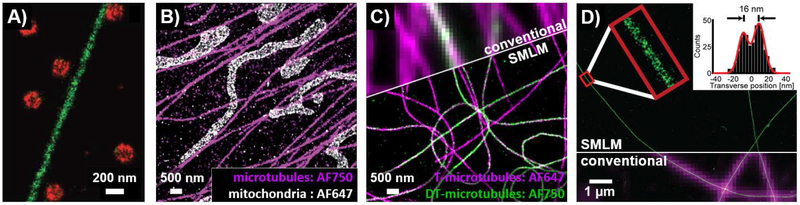
SMLM imaging using cyanine dyes. A) SMLM zoom-in view of a cell immunostained for microtubules (green) and clathrin-coated pits (red) with activator-reporter fluorophore pairs. Alexa Fluor 647 was the reporter fluorophore used on both structures but Cy2 was used as an activator dye on microtubules and a Cy3 was used as an activator dye on clathrin-coated pits. SMLM images of cells immunostained for B) microtubules and mitochondria or C) tyrosinated (T) and detyrosinated (DT) microtubules using multi-reporter imaging with Alexa Fluor 647 and Alexa Fluor 750. D) SMLM image of microtubules grown in vitro, and directly labeled with Cy3B (green, with partial overlay of SMLM image on magenta conventional image); inset shows cross-sectional profile of zoomed in region (red box) with the successful resolution of the inner microtubule walls (~16 nm). In A-C, images were acquired under conditions where fluorophores can reversibly switch on and off, whereas D was acquired using reductive caging as described in the text. From Ref. , adapted with permission from AAAS. Adapted with permission from Ref. , Copyright 2012 John Wiley and Sons. Adapted with permission from Ref. , Copyright 2013 American Chemical Society. Adapted by permission from Springer Customer Service Centre GmbH: Springer Nature, Ref. , Copyright 2012.

Schematic illustration of switching reactions of cyanine fluorophores. A) Cy5 is switched off by BME in the presence of intense red light or by TCEP (without illumination) to form a non-fluorescent adduct in which a thiolate anion or the phosphine TCEP is bound to the γ position of the polymethine bridge, switching it to a nonfluorescent state. Illumination with ultraviolet light dissociates the adduct, returning Cy5 to its bright form. B) Cy3B and other cyanines may be chemically reduced by NaBH4 to a non-fluorescent form which is photoactivatable.

Reversible switching reactions of rhodamine fluorophores. Illumination of a fluorescent rhodamine (green, lower left) in a deoxygenated solution containing a thiol leads to the generation of a nonfluorescent, long-lived radical (upper left) while chemical reduction leads to the generation of a non-fluorescent, reduced rhodamine (lower right). Oxidation or illumination with ultraviolet light can return the radical or reduced rhodamine back to the fluorescent state. The inset diagram illustrates the thiol-induced photo-reduction of the rhodamine triplet state to a radical species (F•) which is followed by oxidation back to the ground state. Adapted from Ref. with permission of The Royal Society of Chemistry (RSC) on behalf of the Centre National de la Recherche Scientifique (CNRS) and the RSC.

Schematic illustration of switching reaction of rhodamine fluorophore via ring opening and intramolecular spirocyclization reactions (top). Examples of spiro-rhodamine dyes used for SMLM are shown (bottom).

A) Structure of two example fluorogenic/chromogenic HaloTag ligands JF646-Halo and JF635-Halo. B) Absorbance enhancement of JF646-Halo and JF635-Halo after binding with HaloTag protein. C) No wash fluorescence imaging of COS7 cells expressing HaloTag-histone H2B fusion and then labeled with JF646-Halo (i), JF635-Halo (ii) and SiTMR-Halo (iii). Scale bar, 15 μm. Adapted by permission from Springer Customer Service Centre GmbH: Springer Nature, Ref. , Copyright 2017.
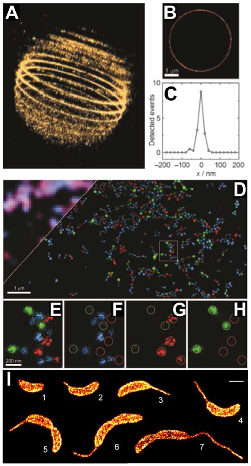
SMLM images obtained using various photoswitchable spiro-lactam rhodamines. A) A 3D SMLM image of a 5 μm silica bead whose surface has been stained with PC-Rh590 and imaged in 16 layers. B) The middle focal plane from A, and C) an associated line profile showing a lateral FHWM of ~30 nm. D-H) Multicolor images of mixtures of silica beads labeled with photoswitchable spiro-lactam rhodamine fluorophores SRA545 (blue), SRA577 (green), and SRA617 (red). I) Montage of SMLM images of C. crescentus cells labeled with RSA-2. Scale bars, 1 μm for B, D and I, 200 nm for E-H. Adapted with permission from Ref. , Copyright 2008 John Wiley and Sons. Adapted with permission from Ref. , Copyright 2008 American Chemical Society. Adapted with permission from Ref. , Copyright 2014 American Chemical Society.

Use of the spontaneously-blinking fluorophore HMSiR for SMLM. A) Single-molecule fluorescence time traces of antibody-bound HMSiR in the absence of thiol and an oxygen-scavenging system. B) Conventional and C) SMLM image of circular, plasmid DNA decorated with HMSiR-labeled RecA filaments. D) Cross-sectional profile of yellow boxed-region in C, showing an apparent ~52 nm width. Scale bars, 500 nm. Adapted by permission from Springer Customer Service Centre GmbH: Springer Nature, Ref. , Copyright 2014.

Photo-activation reactions of rhodamine derivatives by photo-cleavage of diazoketone on spiro-ring (top). Examples of diazoketone caged rhodamine dyes, PA-JF549, PA-JF646 and their corresponding Halo- and SNAP tag ligands (bottom).

A) PA-JF646-Halo can be photoactivated, and when bound to a Halo-tagged protein, the photoactivation yield is improved. Comparison of B) photons per localization per frame and C) track length (number of frames per localization) for PA-JF549-Halo and mEos3.2 showing that PA-JF549-Halo is brighter and produces longer tracks. D) Single-molecule tracking and SMLM in a live embryonic stem cell expressing histone H2B–SNAP-tag and HaloTag-Sox2 labeled with PA-JF646-SNAP and PA-JF549-Halo, respectively; the apparent diffusion rate of Sox2 is lower for the fraction of Sox2 that colocalizes with H2B than for the fraction that does not colocalize (H2B data not shown here). Adapted by permission from Springer Customer Service Centre GmbH: Springer Nature, Ref. , Copyright 2016.

Photo-switching of 4,5-dimethoxy-2-nitrobenzyl (DMNB) group caged rhodamine derivatives by photo-cleavage reaction. Example dyes RhQ8 and BG-cRhod1 used for SR-imaging by SMLM are shown at bottom.

Photoswitching reactions of spiropyran (SP, top) and oxazine-auxochromes (OA, bottom).

70-nm spiropyran nanoparticles as imaged by conventional fluorescence microscopy (top) and SMLM (bottom). Reproduced with permission from Ref. , Copyright 2008 American Chemical Society.
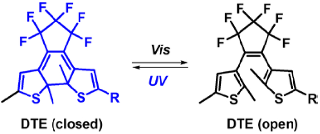
Photoswitching of DTE based on light-induced ring-opening/closing.

Example DCDHF fluorophores (top) and fluorogenic reaction of azido-DCDHFs based on photoactivated conversion of caging groups.

Representative photo-modulation mechanisms of FPs (only the FP chromophores are shown). A) Photoactivatable FPs (PA-FPs) such as PA-GFP convert irreversibly from a native dark from to a green fluorescent form by photo-induced decarboxylation of a glutamate residue (pink arrow) near to the chromophore. B) Photoconvertible FPs (PC-FPs) such as EosFP convert irreversibly from a green fluorescent form to a red fluorescent form upon illumination with violet or ultraviolet light. The photochromic shift occurs due to cleavage of the peptide backbone which extends the conjugation of the chromophore and red-shifts the absorption and emission spectra by 50–60 nm. C) Photoswitchable FPs (PS-FPs) such as Dronpa undergo reversible cis–trans isomerization, where the cis form is fluorescent and the trans form is dark. Note that certain FPs such as PAmCherry and IrisFP may use a combination of these switching mechanisms.
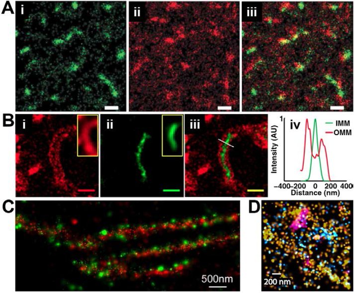
Multicolor SMLM using fluorescent proteins. A) Two-color SMLM in COS-7 cells showing (i) PA-GFP-tagged clathrin light chain (green), (ii) PAmCherry1-tagged transferrin receptor (red), and (iii) overlay. B) Two-color SMLM of mitochondria in EpH4 cells showing outer membrane labeled with (i) PAmCherry1-Lk-BclXl (red), (ii) inner membrane labeled with BCS1L-Lk-rsKame (green), (iii) two-channel overlay, and (iv) intensity profile along white line in iii. C) Two-color SMLM of tdEos-tagged paxillin (green) and PS-CFP2-tagged zyxin (red) in an HFF-1 cell reveals little overlap despite appearing to co-localize using conventional microscopy. D) Three-color SMLM image of Dendra2-hemagglutinin (cyan), PAmCherry1b-actin (yellow), and PAmKate-transferrin receptor (magenta) in fixed HAb2 mouse fibroblast cells. Scale bars are all 500 nm except as indicated otherwise. Adapted by permission from Springer Customer Service Centre GmbH: Springer Nature, Ref. , Copyright 2009. Adapted with permission from Ref. , Copyright 2014 National Academy of Sciences, U. S. A. Adapted with permission from Ref , Copyright 2007 National Academy of Sciences, U. S. A. Adapted from Ref. , Copyright 2011, with permission from Elsevier.

Quantum dot emission spectra are tunable through control of A) particle size and B) particle composition. Reproduced with permission from Ref. , Copyright 2015 American Chemical Society.

Two-color SMLM using QD blueing (stochastic photoconversion). A-B) Widefield and corresponding SMLM fluorescence image of a fixed HepG2 cell immunostained for microtubules with QD565 (cyan) and for mitochondria with QD705 (red). C-F) Zoom-in views of boxed regions from A and B. Scale bars are 2 μm (A-B) and 500 nm (C-F). Reproduced with permission from Ref. , Copyright 2015 American Chemical Society.

SMLM imaging using PAINT (Point Accumulation for Imaging by Nanoscale Topography). A) Conventional fluorescence image and B) corresponding SMLM image of vesicles bound to a coverglass acquired by imaging flashes of light caused by binding of individual molecules of the fluorophore Nile red. Reproduced with permission from Ref. , Copyright 2006 National Academy of Sciences, U. S. A.

SMLM imaging using DNA-PAINT. A) DNA origami structure designed to spell ‘Wyss!’ within an area of ~50 nm × 75 nm. B) Representative SMLM image of a single Wyss! DNA origami and C) a class average obtained from a collection of about 80 imaged origami. Adapted by permission from Springer Customer Service Centre GmbH: Springer Nature, Ref. , Copyright 2016.

A) Volume rendering of an entire dividing LLCPK1 cell imaged by LLS-PAINT. The plasma membrane was labeled with a wheat germ agglutinin-Alexa Fluor 555 probe and intracellular membranes were labeled with BODIPY TR methyl ester. Bounding box is 50 μm × 27 μm × 20 μm. B) Cutaway section through the cell in A revealing various labeled membrane structures and histones (mCherry-H2B, imaged by diffraction-limited imaging prior to LLS-PAINT). Adapted by permission from Springer Customer Service Centre GmbH: Springer Nature, Ref. , Copyright 2016.

A) Fluorogenic reactions of nitro-DCDHF based on enzyme-catalyzed conversion of caging groups. B) Conventional fluorescence image (and corresponding bright-field image, inset) of B. subtilis labeled with nitro-DCDHF. C) SMLM image of blue box area in B, showing localization information of the membrane and punctate spots. D) Temporal progression was revealed for the localizations in the punctate spots (blue dashed box area in C). E) SMLM image of green-boxed region in B. F) Enzyme diffusing was demonstrated in green dashed box area of E. Scale bars: 1 μm (B, C, E); 0.5 μm (D, F). Adapted from Ref. with permission of The Royal Society of Chemistry.

A) Catalyst-enhanced conversion of nonfluorescent resazurin to fluorescent resorufin. B) SMLM image showing a density map of activated resorufin molecules relative to a triangular gold nanoplate. Adapted with permission from Ref. , Copyright 2013 American Chemical Society.

Antibody broadening of features for immunostained microtubules in fixed Ptk2 cells expressing tubulin-YFP. A) Indirect immunostain of tubulin (left), direct immunostain with anti-GFP nanobody on cells expressing tubulin-YFP (middle), and direct immunostain of YFP on cells expressing tubulin-YFP using an anti-GFP antibody (right). B) Cross-sectional profiles for boxed regions in A showing substantially narrower profile using the nanobody. C) Illustration of linkage error using either indirect immunofluorescence with full immunoglobulin G antibodies (left) or direct immunofluorescence with nanobody-based probes (right). Scale bars in A-C are 500 nm. Adapted by permission from Springer Customer Service Centre GmbH: Springer Nature, Ref. , Copyright 2012. Adapted by permission from Springer Customer Service Centre GmbH: Springer Nature, Ref. , Copyright 2015.

Schematic illustration of representative techniques for targeting organic fluorophores to a tagged protein of interest, including A) FlAsH-tag (tetra-Cys tag); B) TMP-tag; C) SNAP-tag, CLIP-tag, and Halo-tag (Nu=nucleophile, F=fluorophore).

Use of affinity-based small molecule labels for SMLM. A) 3D SMLM image of axons in fixed, cultured neurons where filamentous actin is labeled with phalloidin-Alexa Fluor 647 and reveals a periodic membrane-associated cytoskeletal structure. B) SMLM image of mitochondria and the endoplasmic reticiulum in a live BS-C-1 cell labeled using MitoTracker Red and ER-Tracker Red. C) SMLM image of DNA in a live U2OS cell labeled with Picogreen. Scale bars are 500 nm for B, and 2.5 μm for C. From Ref. , adapted with permission from AAAS. Adapted with permission from Ref. , Copyright 2012 National Academy of Sciences, U. S. A. Adapted with permission from Ref. , Copyright 2012 John Wiley and Sons.

SMLM using labeling of nucleic acids by fluorescence in situ hybridization (FISH). A) Conventional fluorescence image of a tetraploid mouse embryonic fibroblast nucleus stained with the general nuclear stain Hoechst 33342 (blue) and FISH probes against Xist RNA (magenta), revealing two inactivated X-chromosomes (zoom-in views, right). B-C) 3D SMLM images of Xist RNA from zoom-in views of A, where distinct Xist puncta are evident at a range of heights (encoded in color). D) SMLM image of telomeres detected using FISH in chromatin from a mouse splenocyte. Adapted with permission from Ref. , Copyright 2015 National Academy of Sciences, U. S. A. Adapted from Ref. , Copyright 2013, with permission from Elsevier.

Use of an expanded genetic code to introduce a non-canonical amino acid into a specific protein of interest at a specific site. Blue box and orange arrow indicate complementary functional groups for biorthogonal reactions and red box indicates the fluorophore (F). Adapted with permission from Ref. , Copyright 2012 John Wiley and Sons.

Conventional image (A) and corresponding SMLM image (B) of synapses in mouse accessory olfactory bulb imaged using activator-reporter pairs. Scale bars are 1 μm for A and B. Adapted from Ref. , Copyright 2010, with permission from Elsevier.

SMLM using A) spectrally-resolved detection for four-channel imaging. The fluorophores Dyomics 634, DyLight 650, CF660C, and CF680 were used to immunolabel peroxisomes, vimentin filaments, microtubules and the outer mitochondrial membrane, respectively, in a fixed PtK2 cell. Although the fluorescence emission spectra overlapped for the four fluorophores B), concurrent spatial and spectral detection allowed discrimination of each fluorophore from the others for multichannel imaging. Adapted by permission from Springer Customer Service Centre GmbH: Springer Nature, Ref. , Copyright 2015.

Four-color Exchange-PAINT image of a cell that has been immunostained for tubulin, mitochondria, peroxisomes, and the Golgi apparatus. Scale bar is 5 μm. Adapted by permission from Springer Customer Service Centre GmbH: Springer Nature, Ref. , Copyright 2014.

Live-cell SMLM reveals nanoscale features and dynamics. A) 3D SMLM images of clathrin-coated pits (CCPs) labeled with Alexa Fluor 647 in live BS-C-1 cells that express clathrin light chain tagged with SNAP (see Section 6.2). B) Two-channel, 3D SMLM image of a CCP with clathrin light chain (magenta) labeled as above and with its cargo transferrin (green) directly labeled with Alexa Fluor 568. C) 2D SMLM image of a cultured hippocampal neuron labeled with Dil showing changes to the dendritic structure including a growing spine or filopodium (green arrowhead), an extending filopodium (blue arrowhead), and a retracting filopodium (magenta arrowhead). Scale bars 100 nm (A, B), 1 μm (C). Panels A-B were acquired in 30 sec, while the snapshots in panel C were obtained in 10 sec. Adapted by permission from Springer Customer Service Centre GmbH: Springer Nature, Ref. , Copyright 2011. Adapted with permission from Ref. , Copyright 2012 National Academy of Sciences, U. S. A.

High density environmentally sensitive (HIDE) probes for live cell SMLM based on the spontaneously-switching fluorophore HMSiR (red, see also Figure 12). A) HIDE probes are synthesized in vivo in a two-step reaction between a trans-cyclooctene-functionalized targeting ligand R that labels an organelle or region of a cell and the tetrazine-functionalized fluorophore HMSiR. The targeting ligand R and labeling conditions can be chosen to label the Golgi, endoplasmic reticulum (ER), mitochondria, or the plasma membrane. B) A SMLM image of the ER in a live HeLa cell acquired in 2 sec using the HIDE probe Cer-HMSiR with partial conventional fluorescence overlay (lower left). This is one snapshot from a series of ~750 spanning ~25 min. Features of the ER are indicated in lowercase including ER sheets (s), ER tubules (t), and fenestrated ER sheets (f). C-D) Several 2 sec snapshots across 25 minutes of acquisition (2 sec per frame) for the boxed regions in B showing dynamic behavior of the ER including budding (yellow arrowheads), looping (green arrowhead), fusion (blue and magenta arrowheads), and reversible transition between tubular and sheet-like morphologies (white arrowheads). E) Kymograph along purple line in B showing the line profile (vertical) as a function of time. Scale bar 500 nm. Adapted by permission from Springer Customer Service Centre GmbH: Springer Nature, Ref. , Copyright 2017.
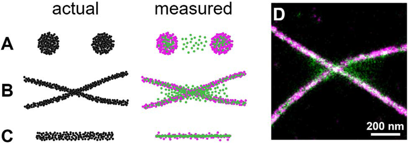
Double-localization artifacts in SMLM. A-C) Cartoon illustration, with actual fluorophore distributions shown in black, measured single-localizations shown in magenta and measured double or multiple localizations shown in green. A) Punctate structures produce double localizations toward the center of each punctum and between puncta that are separated by approximately the diffraction limit or less (~250 nm). B) Filaments show double localizations along the length of the filaments, and are easily mistaken for valid, single localizations. Filaments in close proximity, however, reveal spurious localizations where the two filaments approach each other and/or cross. C) A single filamentous structure with abundant double/multiple localizations will appear artificially narrowed. D) Experimental SMLM image of microtubules in a fixed and immunolabeled BS-C-1 cell recorded under conditions that produced many double/multiple localizations; localizations with large spot widths (more likely to be double/multiple localizations) have been rendered in green while others have been rendered in magenta.

SMLM studies use different metrics to characterize uncertainty in localization, including full-width at half maximum (FHWM) and standard deviation (SD), and it is important to determine which metric is used when comparing performance in different studies. For a Gaussian distribution, FWHM=2.35×SD.
References
-
- Abbe E Beiträge zur Theorie des Mikroskops und der mikroskopischen Wahrnehmung: I. Die Construction von Mikroskopen auf Grund der Theorie. Arch. Für Mikrosk. Anat. 1873, 9, 413–418.
-
- Hell SW Nobel Lecture: Nanoscopy with Freely Propagating Light. Rev. Mod. Phys. 2015, 87, 1169–1181.
-
- Moerner WE (William E . Nobel Lecture: Single-Molecule Spectroscopy, Imaging, and Photocontrol: Foundations for Super-Resolution Microscopy. Rev. Mod. Phys. 2015, 87, 1183–1212. - PubMed
-
- Betzig E Nobel Lecture: Single Molecules, Cells, and Super-Resolution Optics. Rev. Mod. Phys. 2015, 87, 1153–1168. - PubMed
-
- Hell SW Far-Field Optical Nanoscopy. Science 2007, 316, 1153–1158. - PubMed
Publication types
MeSH terms
Substances
Grants and funding
LinkOut - more resources
Full Text Sources
Other Literature Sources
Miscellaneous
