

Finite element analysis of the foot: Stress and displacement shielding
- PMID: 30224853
- PMCID: PMC6139004
- DOI: 10.1016/j.jor.2018.08.037
Finite element analysis of the foot: Stress and displacement shielding
Erratum in
-
Erratum regarding missing Declaration of Competing Interest statements in previously published articles.J Orthop. 2020 Dec 15;24:292. doi: 10.1016/j.jor.2020.12.005. eCollection 2021 Mar-Apr. J Orthop. 2020. PMID: 33994701 Free PMC article.
Abstract
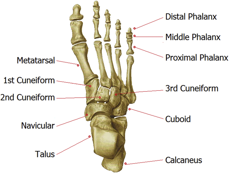
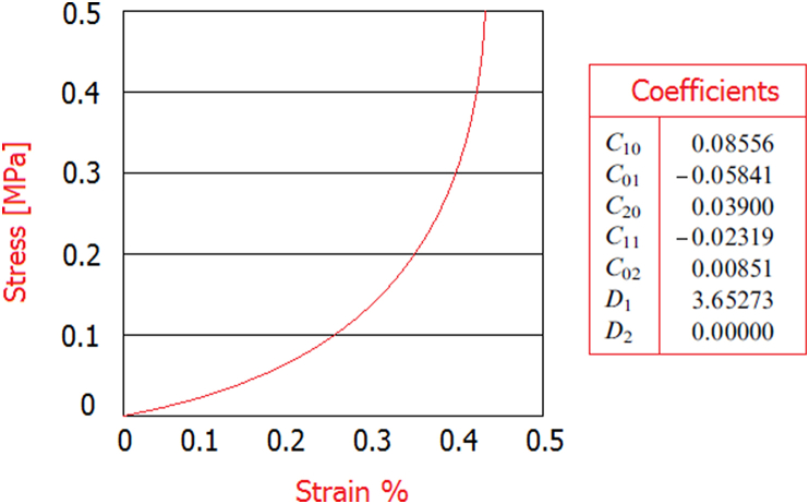
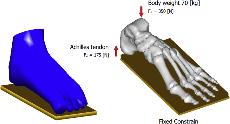
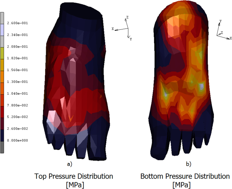
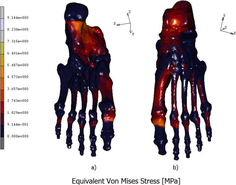
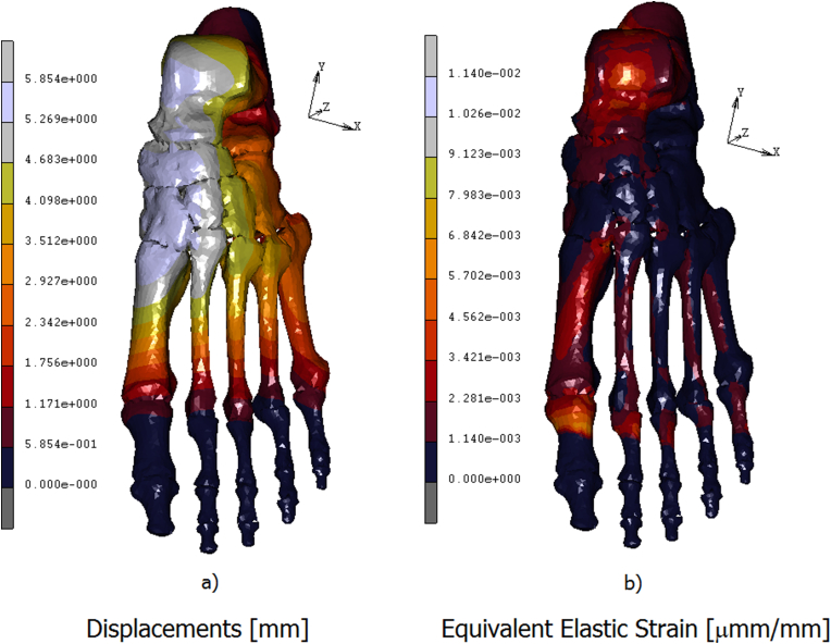
The foot is at the base of the antigravity control system (postural or equilibrium system) that allows the man to assume the upright posture and to move in the space. This podalic cohesion is achieved by the capsulo-ligamentous and aponeurotic formations to which are added the muscular formations with functions of "active ligaments" and postural. A three-dimensional (3D) finite element model of human foot was developed using the real foot skeleton and soft tissue geometry, obtained from the 3D reconstruction of MR images. The plantar fascia and the other main ligaments were simulated using truss elements connected with the bony surfaces. Bony parts and ligaments were encapsulated into a skin of soft tissues, imposing a linear elastic behavior of material in the first case and the hyperelastic law in the second. The model was tested by applying a load of 350 N on the top of the talus and the reaction force applied on the Achilles tendon equal to 175 N acting, and putting it in contact with a rigid wall. The results evidence that the most stressed areas, localized around the calcaneus following a trajectory that includes the cuboid and spreading into metatarsals and first phalanges. The foot is a "spatial" structure perfectly designed to absorb and displace the forces, brought back to the infinite planes of the space.
Keywords: CAD; FE analysis; Foot model.
Figures
References
-
- Patil K.M., Charanya G., Prabhu G.K. Optical pedobarography for assessing neuropathic feet in diabetic patients—a review. Int J Low Extrem Wounds. 2002;1:93–103. - PubMed
-
- Raspovic A., Newcombe L., Lloyd J., Dalton E. Effect of customized insoles on vertical plantar pressures in sites of previous neuropathic ulceration in the diabetic foot. Foot. 2000;10:133–138.
-
- Lord M., Hosein R. A study of in-shoe plantar shear in patients with diabetic neuropathy. Clin BioMech. 2000;15:278–283. - PubMed
-
- Chen W.P., Tang F.T., Ju C.W. Stress distribution of the foot duringmid-stance to push-off in barefoot gait: a 3-D finite element analysis. Clin BioMech. 2001;16:614–620. - PubMed
-
- Gefen A. Plantar soft tissue loading under the medial metatarsals in the standing diabetic foot. Med Eng Phys. 2003;25:491–499. - PubMed
LinkOut - more resources
Full Text Sources
Other Literature Sources
Miscellaneous
