. 2018 Oct 1:308:377-389.
doi: 10.1016/j.jneumeth.2018.09.013. Epub 2018 Sep 16.

Improved methods for MRI-compatible implants in nonhuman primates

Affiliations

Improved methods for MRI-compatible implants in nonhuman primates

Michael Ortiz-Rios et al. J Neurosci Methods. .

Abstract

Background: Neuroscientists commonly use permanently implanted headposts to stabilize the head of nonhuman primates (NHPs) during electrophysiology and functional magnetic resonance imaging (fMRI). Here, we present improved methodology for MRI-compatible implants without the use of acrylic for head stabilization in NHPs.

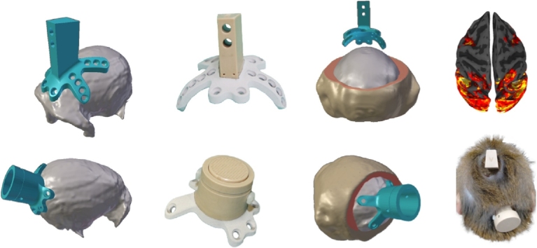
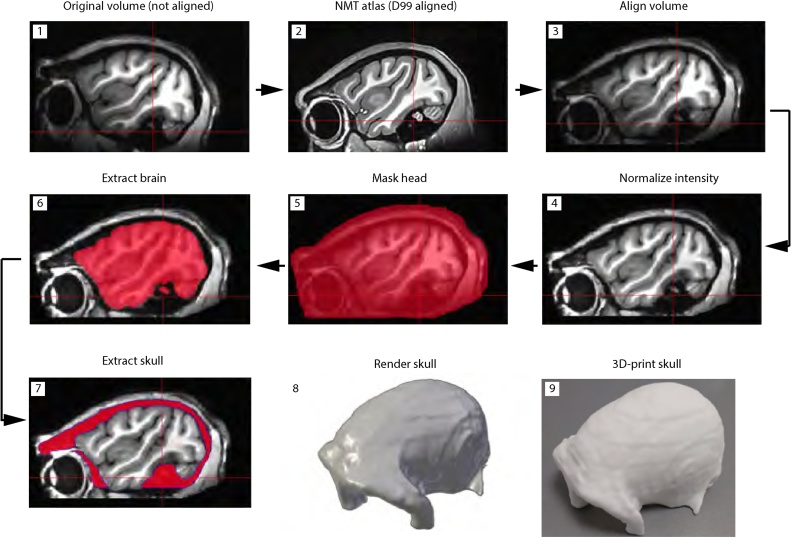
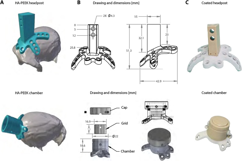
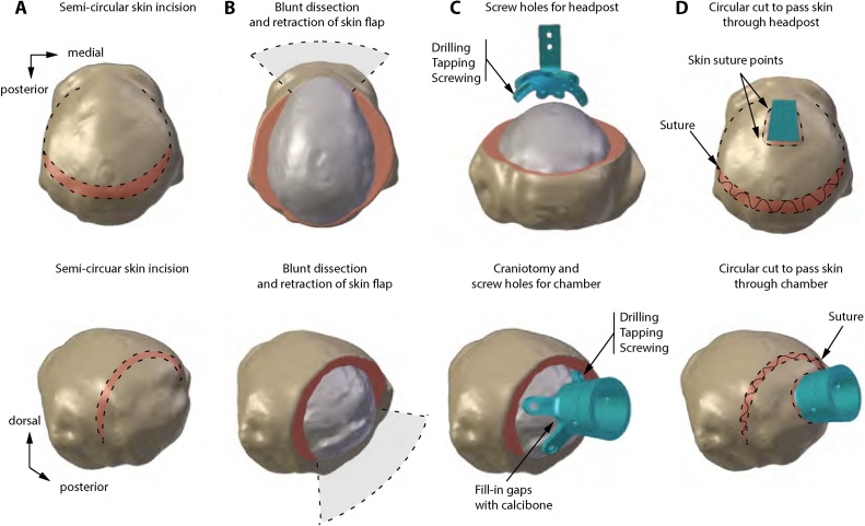
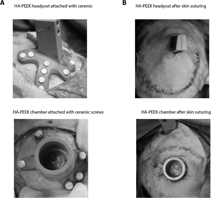
New method: MRI is used to obtain a 3D-reconstruction of NHP skulls, which are used to create customized implants by modeling intersections with the bone. Implants are manufactured from PEEK using computer numerical control machining and coated with hydroxyapatite to promote osseointegration. Surgically, implants are attached to the skull with ceramic screws, while the skin flap is pulled over the implant and closed subcutaneously.

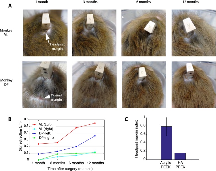
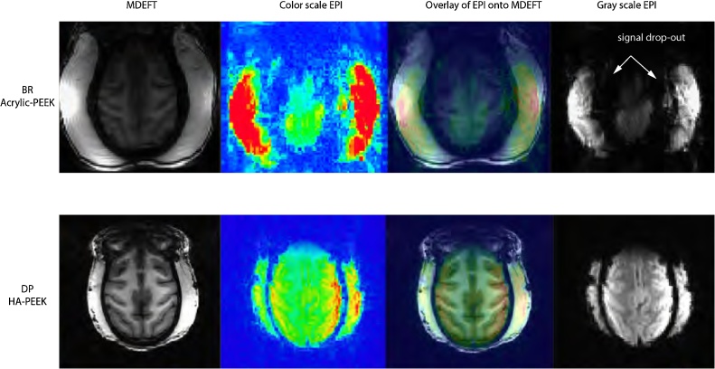
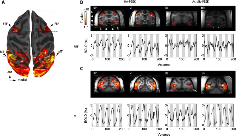
Results: Quality of blood oxygen level dependent (BOLD) fMRI signal is improved in animals implanted with our method as compared to traditional acrylic implants. Additionally, implants are well-integrated with the skull, remain robust for more than a year and without granulation tissue around the skin margin.

Comparison with existing method(s): Previous improvements on NHP implants (Chen et al., 2017; McAndrew et al., 2012; Mulliken et al., 2015; Overton et al., 2017) lacked fMRI-compatibility, as they relied on titanium headposts and/or titanium screws. Thus, most fMRI studies in NHPs today still rely on the use of acrylic-based headposts for stabilization and the use of contrast-enhanced agents to improve MRI signal.

Conclusions: Our method preserves fMRI-compatibility and results in measurable improvement in BOLD signal without the use of contrast-enhanced agents. Furthermore, the long-term stability of our implants contributes positively to the wellbeing of NHPs in neuroscience research.

Keywords: Acrylic; Electrophysiology; Functional magnetic resonance imaging (fMRI); Hydroxyapatite (HA); Implant; Macaque; Osseointegration; Polyetheretherketone (PEEK).


Figures

None
Graphical abstract
Fig. 1
Fig. 1
Workflow of anatomical MRI data pre-processing for implant design and surgical planning. Prior to the process of skull extraction, the T1 volume is aligned to the NMT template, which is further aligned with the D99 atlas space. Spatial intensity distributions are used to normalize the volume from surface coil inhomogeneities. The head and brain are segmented and subtracted from the normalized volume. Manual editing is done to remove non-skull voxels. The skull volume is rendered in STL format and 3D printed for surgical planning.
Fig. 2
Fig. 2
Implant design based on the intersection with the skull surface. Implant designs for headpost (top) and chamber (bottom). A. STL files of HA-PEEK implants and rendered skull showing a tight surface intersection between the implants and the skull. B. Drawings and design features of headpost and chamber. The base of the headpost includes four legs for anchoring the implant around the circumference of the skull. The implant’s trapezoid-shaped part at the top is used to fix the animal’s head onto a head holder piece. The chamber includes a grid for electrophysiological recordings and a cap that is used to separate the craniotomy from the external environment. The holes on the legs of each of the implants were made to fit Thomas Recording ceramic screws. C. Images of the headpost and chamber before surgery showing hydroxyapatite (HA) coating.
Fig. 3
Fig. 3
Surgical approach for anchoring MRI-compatible implants. Headpost and chamber implant surgery based on stereotaxic and MRI coordinates. A. The semi-circular skin incision shows the exposure of the fascia. B. Dissection of the fascia and exposure of the bone. The skin flap is retracted and maintained moist. Connective tissue is scraped from the skull and the temporal muscles retracted to facilitate placement of the implant. C. Drilling, tapping, and screwing allows locking the implant in place with ceramic screws. For chamber surgery, bone substitute material (Calcibon) serves to fill gaps between the chamber and the skull. D. The fascia is sutured, the skin is cut to allow passage of the implant through the skin. Finally, a subcutaneous suture is made to close the incision.
Fig. 4
Fig. 4
Close-fitting of implants during and after surgery. A. Example image during surgery showing the tight fit of the HA-PEEK implants to the skull, and ceramic screw heads. B. Image after subcuticular suture to cover the skin over the implant. The chamber image (bottom) shows the central craniotomy with dura mater exposed.
Fig. 5
Fig. 5
State of wound and implant margin over the course of one year. A. Images of monkeys VL and DP showing the wound and headpost margins over the course of one year. Overall, the HA-PEEK headpost implants for both animals healed in less than 3-months. Monkey DP had a small scar tissue of approximately 1 cm in length as a result of scratching the incision (similarly to monkey FL, see Section 3 for details). However, over the course of the year, the incision remained stable and the implant margin remained free of granulation tissue or infection even without regular cleaning. B. After one year, we observed a small retraction of the skin, approximately of 0.5 cm in both animals.
Fig. 6
Fig. 6
Protective cap worn after surgery to prevent wound picking. A. Animal FL showed persistent scratching of the wound margin that prevented wound healing. B. Protective cap made out of fiber-glass material with small perforations that allow airflow around the skin margin. C. The cap protected the animal from self-inducing wounds around the implant and contributed to the overall healing of the wound margin D.
Fig. 7
Fig. 7
Comparison of anatomical and functional images between monkeys with HA-PEEK and Acrylic-PEEK implants. Example anatomical and functional MRI images obtained from two monkeys (top, Acrylic-PEEK; bottom, HA-PEEK) showing the effects of the implants on MRI signal quality. For comparison, each image is shown at the same axial distance, at which the implant surrounds the most dorsal part of the brain. Acrylic-based implants may require the deflexion of the temporal muscles leading to an air-filled gap along the margin which causes abrupt changes in magnetic field susceptibility around the transition zones (e.g. bone/acrylic to brain tissue).
Fig. 8
Fig. 8
Functional activation of frontal eye fields in monkeys with HA-PEEK implants but not Acrylic-PEEK implants. A. Brain surface reconstruction of monkey DP showing the overall visually evoked response during movie viewing. The activation pattern includes regions in the frontal eye fields (FEF) and the middle temporal area (MT). B. (Top) Coronal slices taken at the level corresponding to the anterior dashed line in A, in each individual monkey. Each animal was presented with periods of natural movies interleaved with periods of black screen and was allowed to freely look around and watch the movie. (Bottom) Example time courses for each monkey show the overall % BOLD modulation to 30-s movie segments (white background) and 30 s off-period (grey background). Notice the lack of activation and BOLD modulation in the FEF region for monkeys DL and BR with acrylic based headposts. C. Similar to B, except coronal slices are centered on area MT (posterior dashed line in A) and show % BOLD modulation plots. All data were obtained from a single run session (5 min of scanning) and illustrated using the same threshold level (q FDR = 0.05, p < 0.01, significance t-values > 1.9 and clipped at 10 for comparisons across animals). DP (T-value range 1.74–17.7; VL (T-value range 2.14–13.3; DL. (T-value range 2.52–13.5); BR (T-value range 2.50–10.8).

References

    1. Chen X., Possel J.K., Wacongne C., van Ham A.F., Klink P.C., Roelfsema P.R. 3D printing and modelling of customized implants and surgical guides for non-human primates. J. Neurosci. Methods. 2017;286:38–55. - PMC - PubMed
    1. Cox R.W. AFNI: software for analysis and visualization of functional magnetic resonance neuroimages. Comput. Biomed. Res. 1996;29:162–173. - PubMed
    1. Ekstrom L.B., Roelfsema P.R., Arsenault J.T., Bonmassar G., Vanduffel W. Bottom-up dependent gating of frontal signals in early visual cortex. Science (80-.) 2008;321:414–417. - PMC - PubMed
    1. Eley K.A., Mcintyre A.G., Watt-Smith S.R., Golding S.J. “Black bone” MRI: a partial flip angle technique for radiation reduction in craniofacial imaging. Br. J. Radiol. 2012;85:272–278. - PMC - PubMed
    1. Goense J.B.M., Ku S.P., Merkle H., Tolias A.S., Logothetis N.K. fMRI of the temporal lobe of the awake monkey at 7 T. Neuroimage. 2008;39:1081–1093. - PubMed

Publication types