. 2018 Feb 13;95(2):267-275.
doi: 10.1021/acs.jchemed.7b00506. Epub 2017 Dec 15.

Lab-on-a-Chip: Frontier Science in the Classroom

Affiliations

Lab-on-a-Chip: Frontier Science in the Classroom

Jan Jaap Wietsma et al. J Chem Educ. .

Abstract

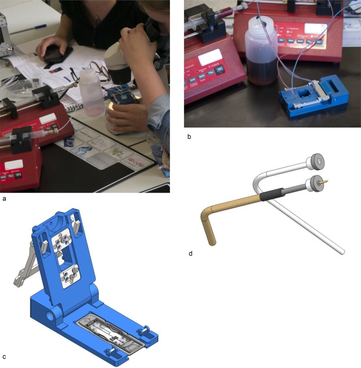
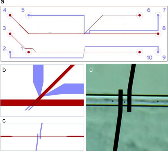
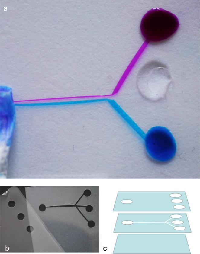
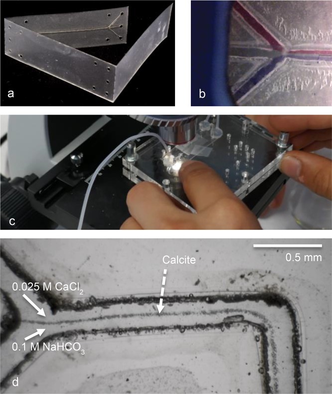
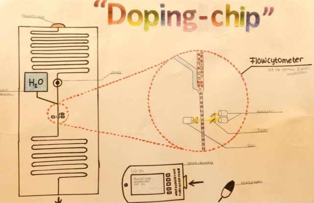
Lab-on-a-chip technology is brought into the classroom through development of a lesson series with hands-on practicals. Students can discover the principles of microfluidics with different practicals covering laminar flow, micromixing, and droplet generation, as well as trapping and counting beads. A quite affordable novel production technique using scissor-cut and laser-cut lamination sheets is presented, which provides good insight into how scientific lab-on-a-chip devices are produced. In this way high school students can now produce lab-on-a-chip devices using lamination sheets and their own lab-on-a-chip design. We begin with a review of previous reports on the use of lab-on-a-chip technology in classrooms, followed by an overview of the practicals and projects we have developed with student safety in mind. We conclude with an educational scenario and some initial promising results for student learning outcomes.


Conflict of interest statement

The authors declare no competing financial interest.

Figures

Figure 1
Figure 1
Educational lab-on-a-chip setup: (a) Learners using the lab-on-a-chip setup in the classroom. (b) The educational setup demonstrating laminar flow in the H-reactor (see Figure 2). (c) The design of the chip holder. (d) Detail showing the fluidic and electronic connectors.
Figure 2
Figure 2
(a) Laminar flow in the H-reactor, observable macroscopically in the tubing (see also Figure 1b) and (b) with low magnification on the chip. Tubings on the left are used as inlets, with a flow rate of about 200 μL/min. The bar is 10 mm. The H-reactor is produced from borosilicate glass, using negative dry film resist and powder blasting, and has a channel width of 150–200 μm and channel depth of 150 μm.
Figure 3
Figure 3
Mixer chip: (a) Layout of the mounted teardrop mixer chip (45 mm long, 15 mm wide). (b) Enlarged view of the teardrop mixing element. Channel width is 150–200 μm, and the channel depth is 150 μm. The mixer chip is produced from borosilicate glass, using negative dry film resist and powder blasting.
Figure 4
Figure 4
Droplet chip: (a) Layout of the focused flow droplet generator (45 mm long, 15 mm wide), with channel width 500 μm, channel depth 100 μm, nozzle width 160 μm, and nozzle depth 60 μm. (b) Formation of oil droplets in water, which is the experiment being performed by learners using the chip in Figure 1. The chip is produced from borosilicate glass, using positive resist and a wet etching (HF) technique.
Figure 5
Figure 5
TCB chip for trapping and counting of beads: (a) Layout of the TCB chip (45 mm long, 15 mm wide). Channels (25 μm deep) are shown in red, with inlets labeled 1 (channel 70 μm wide; near the electrodes 54 μm wide), 3 (channel 70 μm wide), 4 (channel 150 μm wide), outlets labeled 6 (branch 70 μm wide), 8, 10; electrode paths (made of Pt, placed in etched and TiO coated paths) are shown in blue, with connections labeled 2, 5, 7, 9. (b) Layout of the channels and electrodes used for trapping beads or cells (electrode tips 15 μm wide). (c) Tips of the sensing electrodes (tips 25 μm wide) at the bottom of the channel (54 μm wide, as described by Segerink et al.). (d) Microscopic view of 6 μm beads passing through the channel depicted in part c. The chip is made from borosilicate glass, using positive resist and a wet etching (HF) technique.
Figure 6
Figure 6
Fabrication of demonstration chips from commercial hot-lamination foil (about 80 μm thickness), using a standard office punch (6 mm punch diameter), fine scissors, and hot-lamination machine. (a) The finished chip, showing laminar flow using diluted printer inks (1:10) and water. The fluids are transported by capillary force, and propagated using tissue paper at the outlet. Channel width is about 1.5 mm. Chip outer dimensions: 50 × 60 mm. (b) Top layer (holes only, left) and middle layer (holes and channels, right). The bottom layer is untreated. (c) Schematic of the chip layers.
Figure 7
Figure 7
Laser-cut demonstration chips, which can be modified or redesigned by learners. (a) Laser-cut foil chip, made from 80 mm GBC High Speed laminator foil. The chips produced (outer dimensions 45 mm long, 15 mm wide, and 0.24 mm thick) are fitted on top of a 1 mm thick support plate, in the mount of the lab-on-a-chip holder. (b) The first prototype chip, showing trilaminar flow, in the chip holder. (c) A laser-cut Y reactor chip, mounted in the acrylic glass (PMMA) holder, connected with silicone ferrules. In this experiment the formation of calcite precipitate is studied, as described by Chia et al. (d) Calcite precipitate visible in the first part of a laser-cut serpentine mixer channel (width 100 μm, produced from 125 μm thick Leitz foil), from 0.025 M CaCl2 and 0.1 M NaHCO3 solution with syringe pumps at a flow speed of 45 μL/min. All details of the design of the foil chips and the PMMA holder are described in the Supporting Information.
Figure 8
Figure 8
Student poster presenting the idea for doping detection by red blood cell counting in blood, one of the outcomes of a lab-on-a-chip project conducted at secondary schools (reproduced with permission).

Similar articles

Cited by

References

    1. Fintschenko Y. Education: a modular approach to microfluidics in the teaching laboratory. Lab Chip 2011, 11, 3394–3400. 10.1039/c1lc90069b. - DOI - PubMed
    1. Bridle H.; Morton J.; Cameron P.; Desmulliez M. P. Y.; Kersaudy- Kerhoas M. Design of problem-based learning activities in the field of microfluidics for 12- to 13-year-old participants—Small Plumbing!: empowering the next generation of microfluidic engineers. Microfluid. Nanofluid. 2016, 20, 103.10.1007/s10404-016-1770-x. - DOI
    1. Hemling M.; Crooks J. A.; Oliver P. M.; Brenner K.; Gilbertson J.; Lisensky G. C.; Weibel D. B. Microfluidics for high school chemistry students. J. Chem. Educ. 2014, 91, 112–115. 10.1021/ed4003018. - DOI - PMC - PubMed
    1. Piunno P. A. E.; Zetina A.; Chu N.; Tavares A. J.; Noor M. O.; Petryayeva E.; Uddayasankar U.; Veglio A. A comprehensive microfluidics device construction and characterization module for the advanced undergraduate analytical chemistry laboratory. J. Chem. Educ. 2014, 91, 902–907. 10.1021/ed400728a. - DOI
    1. Chia M. C.; Sweeney C. M.; Odom T. W. Chemistry in microfluidic channels. J. Chem. Educ. 2011, 88, 461–464. 10.1021/ed1008624. - DOI

LinkOut - more resources