. 2018 Sep 28;18(10):3261.
doi: 10.3390/s18103261.

An Adaptive Zero Velocity Detection Algorithm Based on Multi-Sensor Fusion for a Pedestrian Navigation System

Affiliations

An Adaptive Zero Velocity Detection Algorithm Based on Multi-Sensor Fusion for a Pedestrian Navigation System

Ming Ma et al. Sensors (Basel). .

Abstract

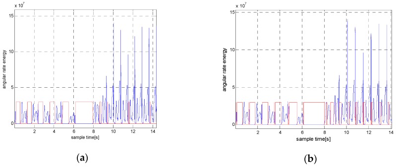
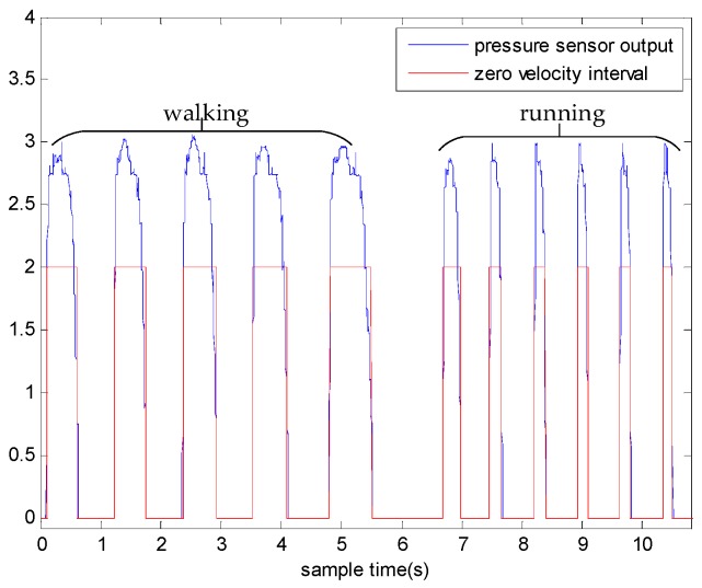
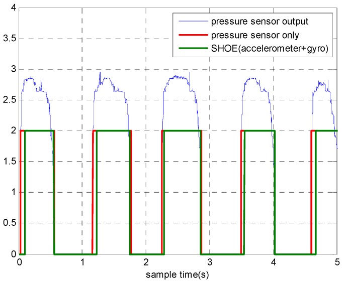
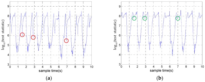
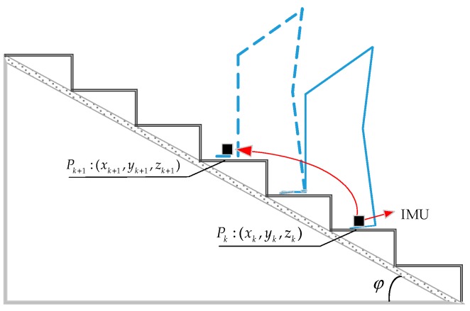
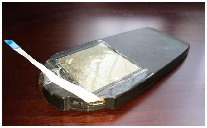
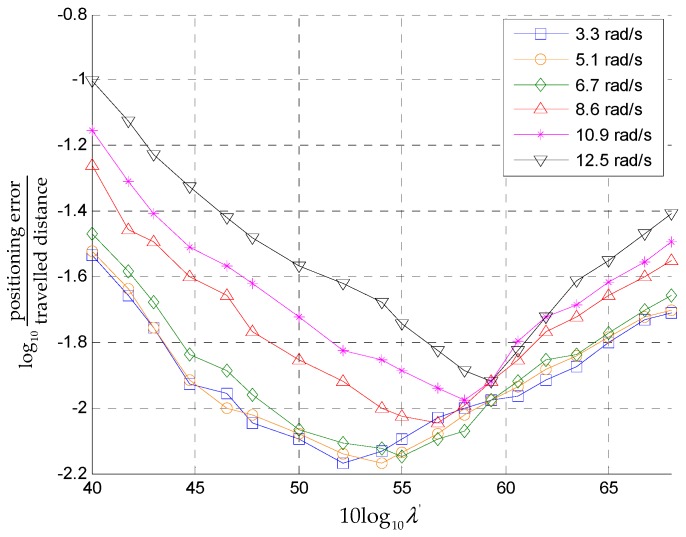
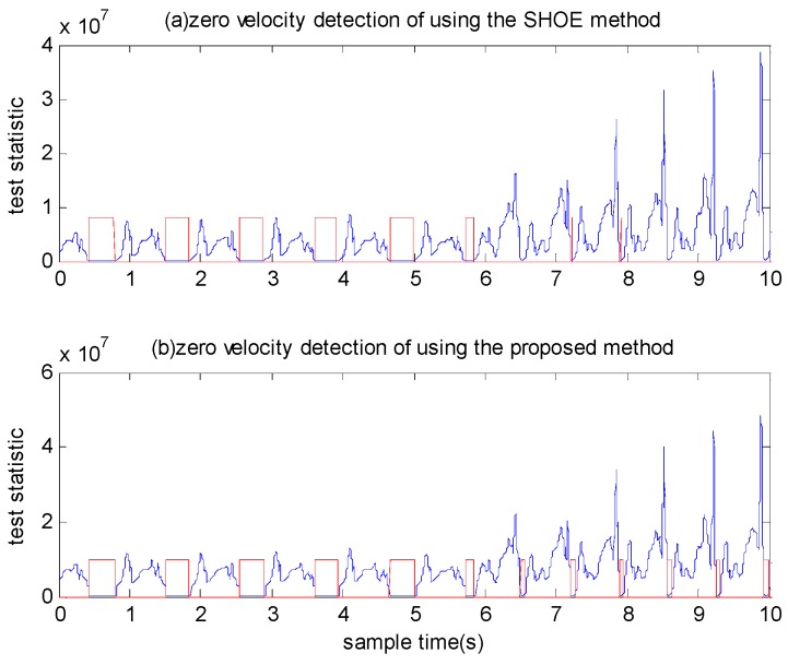
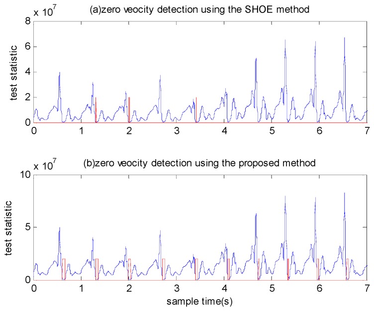
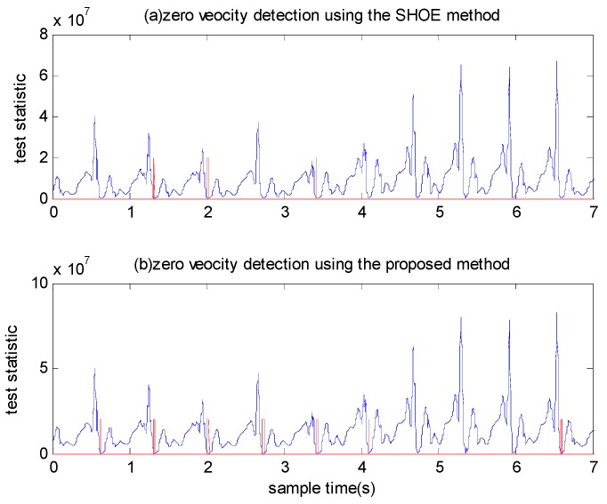
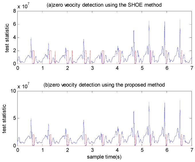
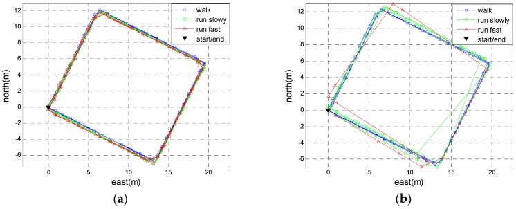
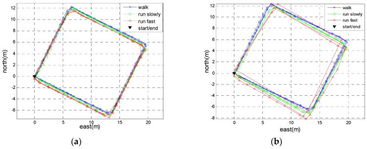
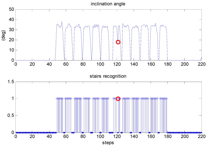
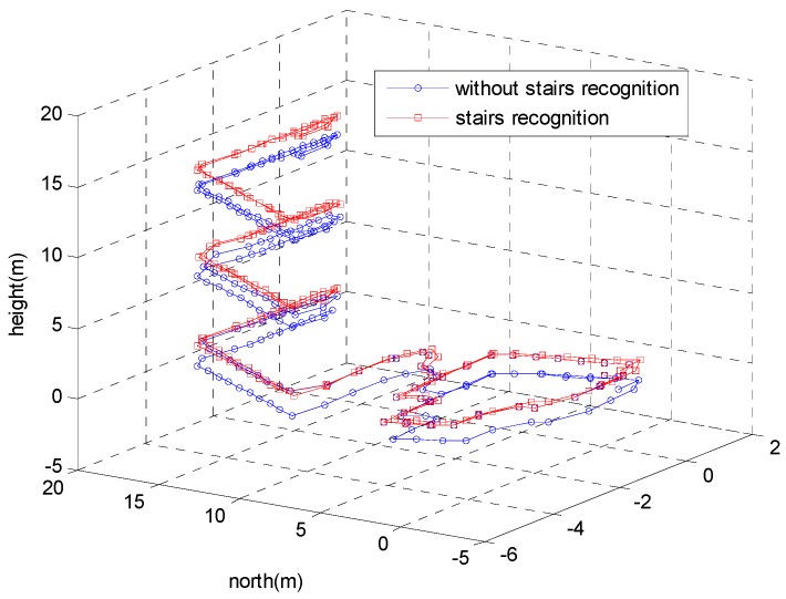
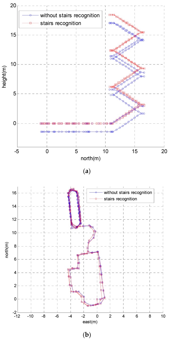
The zero velocity update (ZUPT) algorithm is an effective way to suppress the error growth for a foot-mounted pedestrian navigation system. To make ZUPT work properly, it is necessary to detect zero velocity intervals correctly. Existing zero velocity detection methods cannot provide good performance at high gait speeds or stair climbing. An adaptive zero velocity detection approach based on multi-sensor fusion is proposed in this paper. The measurements of an accelerometer, gyroscope and pressure sensor were employed to construct a zero-velocity detector. Then, the adaptive threshold was proposed to improve the accuracy of the detector under various motion modes. In addition, to eliminate the height drift, a stairs recognition method was developed to distinguish staircase movement from level walking. Detection performance was examined with experimental data collected at varying motion modes in real scenarios. The experimental results indicate that the proposed method can correctly detect zero velocity intervals under various motion modes.

Keywords: ZUPT; adaptive threshold; pedestrian navigation system; stairs recognition; zero velocity detection.


Conflict of interest statement

The authors declare no conflict of interest.

Figures

Figure 1
Figure 1
The zero velocity detection results of the SHOE method when a pedestrian is walking and running. (a) The detection result using a small threshold. (b) The detection result using a large threshold. The red line denotes the stationary state and moving state. Small values indicate the moving state, while large values indicate the stationary state.
Figure 2
Figure 2
The measurements of the pressure sensor during walking and running.
Figure 3
Figure 3
The detection results of zero velocity intervals.
Figure 4
Figure 4
The test statistics of zero velocity intervals: (a) The test statistics of the SHOE detector. (b) The test statistics of the proposed detector.
Figure 5
Figure 5
The foot-mounted inertial navigation system.
Figure 6
Figure 6
The y-axis gyroscope output of the four motion modes: walking slowly, walking fast, running slowly and running fast.
Figure 7
Figure 7
The zero velocity detection results when a pedestrian ascends stairs using the optimal detection threshold of level walking.
Figure 8
Figure 8
The height drift caused by incorrect zero interval detection.
Figure 9
Figure 9
Sketch of ascending stairs.
Figure 10
Figure 10
The insole-shaped MIMU module.
Figure 11
Figure 11
The positioning error as a function of the detection threshold.
Figure 12
Figure 12
The zero velocity interval detection comparison between when a person is walking and running slowly.
Figure 13
Figure 13
The zero velocity interval detection comparison between when a person is running slowly and running fast.
Figure 14
Figure 14
The zero velocity interval detection comparison using a fixed threshold for both detectors when a person is running slowly and running fast.
Figure 15
Figure 15
The zero velocity interval detection comparison using adaptive threshold for both detectors when a person is running slowly and running fast.
Figure 16
Figure 16
The step-wise trajectories of Person A. (a) The trajectories using the proposed method. (b) The trajectories using the SHOE method.
Figure 17
Figure 17
The step-wise trajectories of Person B. (a) The trajectories using the proposed method. (b) The trajectories using the SHOE method.
Figure 18
Figure 18
The inclination angle of the trajectory and the result of stairs recognition.
Figure 19
Figure 19
The 3D trajectories of the proposed method with stairs recognition versus without stairs recognition.
Figure 20
Figure 20
The 2D trajectories of the proposed method with stairs recognition versus without stairs recognition. (a) The calculated trajectories in the yz plane. (b) The calculated trajectories in xy plane.

References

    1. Zhang R., Hoflinger F., Reindl L. Inertial sensor based indoor localization and monitoring system for emergency responders. IEEE Sens. J. 2013;13:838–848. doi: 10.1109/JSEN.2012.2227593. - DOI
    1. Bird J., Arden D. Indoor navigation with foot-mounted strapdown inertial navigation and magnetic sensors [Emerging Opportunities for Localization and Tracking] IEEE Wirel. Commun. 2011;18:28–35. doi: 10.1109/MWC.2011.5751293. - DOI
    1. Gu Y., Song Q., Li Y., Ma M., Zhou Z. An anchor-based pedestrian navigation approach using only inertial sensors. Sensors. 2016;16:334. doi: 10.3390/s16030334. - DOI - PMC - PubMed
    1. Skog I., Nilsson J.O., Handel P. Pedestrian tracking using an IMU array; Proceedings of the IEEE International Conference on Electronics, Computing and Communication Technologies; Bangalore, India. 6–7 January 2014; pp. 1–4.
    1. Gu Y., Song Q., Li Y., Ma M. Foot-mounted pedestrian navigation based on particle filter with an adaptive weight updating strategy. J. Navigat. 2015;68:23–38. doi: 10.1017/S0373463314000496. - DOI

LinkOut - more resources