

The difference of stress distribution of maxillary expansion using rapid maxillary expander (RME) and maxillary skeletal expander (MSE)-a finite element analysis
- PMID: 30280257
- PMCID: PMC6168444
- DOI: 10.1186/s40510-018-0229-x
The difference of stress distribution of maxillary expansion using rapid maxillary expander (RME) and maxillary skeletal expander (MSE)-a finite element analysis
Abstract
Background: Maxillary skeletal expander (MSE) in combination with miniscrews was developed to overcome the drawbacks that may have resulted from the application of conventional rapid maxillary expander (RME). This research was conducted to analyze the difference of stress distribution of maxillary expansion using RME and MSE in the region of interests (ROIs): first molars (M1), palatal alveolar bones of M1, palatine sutures, zygomatic sutures, miniscrews, and their surrounding bones.
Methods: A dry skull was scanned using CBCT and rendered into a three-dimensional (3D) model of craniomaxillary structures. The data analysis was done both visually and numerically.
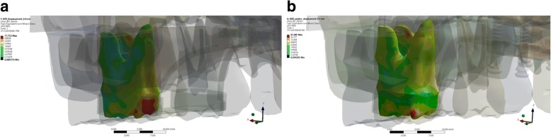
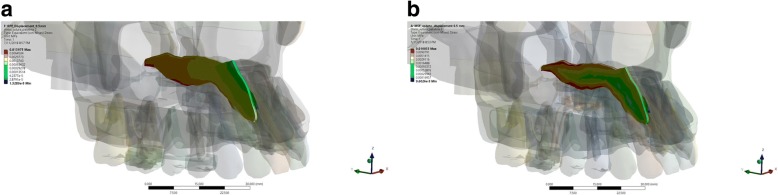
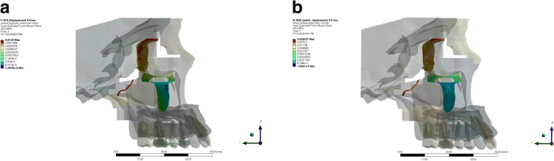
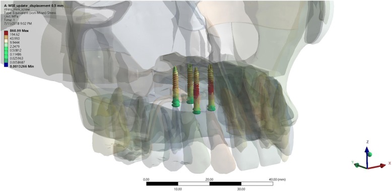
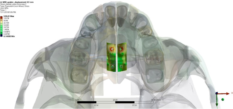
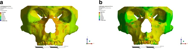
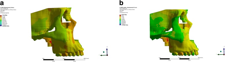
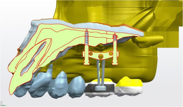
Result: The stress distributions in RME group were located at the palatal side of M1, mesial side of palatal alveolar of M1, pulp chamber of M1, and inferior cortex of palatine sutures. The stress distributions in the MSE group were located at the distopalatal cusp of M1, palatal side of palatal alveolar of M1, and inferior and superior cortex of palatine sutures. The stress distributions in zygomatic sutures on both groups were located at the zygomaticotemporal sutures, whereas in the miniscrews, the stress were located at the anterior miniscrews and palatal side of surrounding bones.
Conclusions: There were significant differences of stress distribution of maxillary expansion measured in the ROIs in the craniomaxillary 3D model using RME and MSE.
Keywords: Finite element analysis (FEA); Maxillary skeletal expander (MSE); Rapid palatal expander (RME); Stress distribution.
Conflict of interest statement
Ethics approval and consent to participate
Not applicable.
Consent for publication
Not applicable.
Competing interests
The authors declare that they have no competing interests.
Publisher’s Note
Springer Nature remains neutral with regard to jurisdictional claims in published maps and institutional affiliations.
Figures


Similar articles
-
Comparison of stress distribution and displacement pattern of maxillary expansion in craniomaxillary complex using rapid maxillary expander and maxillary skeletal expander: A finite element model analysis.Int Orthod. 2025 Sep;23(3):100997. doi: 10.1016/j.ortho.2025.100997. Epub 2025 Mar 26. Int Orthod. 2025. PMID: 40147292
-
Zygomaticomaxillary modifications in the horizontal plane induced by micro-implant-supported skeletal expander, analyzed with CBCT images.Prog Orthod. 2018 Oct 22;19(1):41. doi: 10.1186/s40510-018-0240-2. Prog Orthod. 2018. PMID: 30345476 Free PMC article.
-
Comparison of the Effects of Different Palatal Morphology on Maxillary Expansion via RME and MSE: A Finite Element Analysis.Clin Exp Dent Res. 2024 Oct;10(5):e70005. doi: 10.1002/cre2.70005. Clin Exp Dent Res. 2024. PMID: 39295434 Free PMC article.
-
Role of the midpalatal suture in FEA simulations of maxillary expansion treatment for adolescents: a review.Int Orthod. 2013 Jun;11(2):119-38. doi: 10.1016/j.ortho.2013.02.001. Epub 2013 Mar 26. Int Orthod. 2013. PMID: 23537640 Review. English, French.
-
Dento-skeletal effects produced by rapid versus slow maxillary expansion using fixed jackscrew expanders: a systematic review and meta-analysis.Eur J Orthod. 2021 Jun 8;43(3):301-312. doi: 10.1093/ejo/cjaa086. Eur J Orthod. 2021. PMID: 33950178
Cited by
-
Surgical and orthodontic rapid palatal expansion in adults using a modified palatal partial osteotomy technique (ppot): Technique description and clinical experience.J Clin Exp Dent. 2020 Jun 1;12(6):e610-e614. doi: 10.4317/jced.56313. eCollection 2020 Jun. J Clin Exp Dent. 2020. PMID: 32665823 Free PMC article.
-
Effect of the computer-aided static navigation technique on the accuracy of bicortical mini-implants placement site for maxillary skeletal expansion appliances: an in vitro study.BMC Oral Health. 2023 Feb 11;23(1):86. doi: 10.1186/s12903-023-02785-7. BMC Oral Health. 2023. PMID: 36774459 Free PMC article.
-
Comparison of 3D-printed and laboratory-fabricated Hyrax on stress distribution and displacement of the maxillary complex: a 3D finite element study.Prog Orthod. 2024 Mar 18;25(1):11. doi: 10.1186/s40510-024-00510-w. Prog Orthod. 2024. PMID: 38494544 Free PMC article.
-
Evaluation of pterygomaxillary disjunction on skeletal and dental changes after surgically assisted rapid maxillary expansion: A systematic review and meta-analysis.Heliyon. 2024 Oct 19;10(20):e38872. doi: 10.1016/j.heliyon.2024.e38872. eCollection 2024 Oct 30. Heliyon. 2024. PMID: 39498079 Free PMC article. Review.
-
Observational Study Regarding Possible Side Effects of Miniscrew-Assisted Rapid Palatal Expander (MARPE) with or without the Use of Corticopuncture Therapy.Biology (Basel). 2021 Mar 3;10(3):187. doi: 10.3390/biology10030187. Biology (Basel). 2021. PMID: 33802266 Free PMC article.
References
-
- Iseri H. Introduction. Semin Orthod. 2012;18(2):99. doi: 10.1053/j.sodo.2011.10.008. - DOI
MeSH terms
LinkOut - more resources
Full Text Sources
