

High Speed, High Density Intraoperative 3D Optical Topographical Imaging with Efficient Registration to MRI and CT for Craniospinal Surgical Navigation
- PMID: 30291261
- PMCID: PMC6173775
- DOI: 10.1038/s41598-018-32424-z
High Speed, High Density Intraoperative 3D Optical Topographical Imaging with Efficient Registration to MRI and CT for Craniospinal Surgical Navigation
Abstract
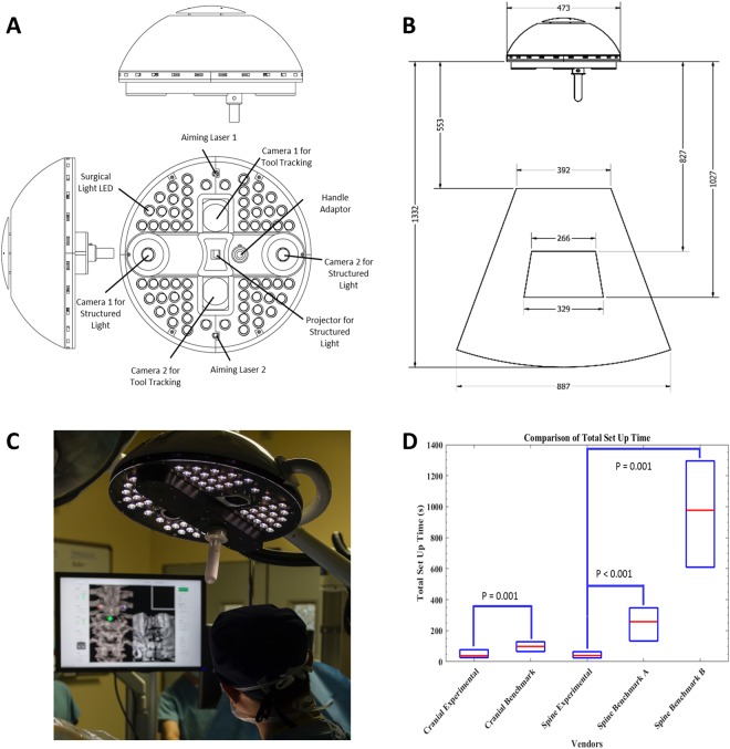
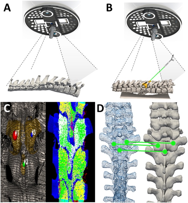
Intraoperative image-guided surgical navigation for craniospinal procedures has significantly improved accuracy by providing an avenue for the surgeon to visualize underlying internal structures corresponding to the exposed surface anatomy. Despite the obvious benefits of surgical navigation, surgeon adoption remains relatively low due to long setup and registration times, steep learning curves, and workflow disruptions. We introduce an experimental navigation system utilizing optical topographical imaging (OTI) to acquire the 3D surface anatomy of the surgical cavity, enabling visualization of internal structures relative to exposed surface anatomy from registered preoperative images. Our OTI approach includes near instantaneous and accurate optical measurement of >250,000 surface points, computed at >52,000 points-per-second for considerably faster patient registration than commercially available benchmark systems without compromising spatial accuracy. Our experience of 171 human craniospinal surgical procedures, demonstrated significant workflow improvement (41 s vs. 258 s and 794 s, p < 0.05) relative to benchmark navigation systems without compromising surgical accuracy. Our advancements provide the cornerstone for widespread adoption of image guidance technologies for faster and safer surgeries without intraoperative CT or MRI scans. This work represents a major workflow improvement for navigated craniospinal procedures with possible extension to other image-guided applications.
Conflict of interest statement
A further development of this technology has received FDA clearance and Health Canada approval with V.X.D.Y., B.A.S., M.K.L., A.M., K.L., P.S., L.d.C. and D.W.C. declaring conflict of interest including intellectual property/equity rights.
Figures
Similar articles
-
Intraoperative image updating for brain shift following dural opening.J Neurosurg. 2017 Jun;126(6):1924-1933. doi: 10.3171/2016.6.JNS152953. Epub 2016 Sep 9. J Neurosurg. 2017. PMID: 27611206 Free PMC article.
-
Technology improvements for image-guided and minimally invasive spine procedures.IEEE Trans Inf Technol Biomed. 2002 Dec;6(4):249-61. doi: 10.1109/titb.2002.806089. IEEE Trans Inf Technol Biomed. 2002. PMID: 15224839 Review.
-
Learning curve analysis of 3D-fluoroscopy image-guided pedicle screw insertions in lumbar single-level fusion procedures.Arch Orthop Trauma Surg. 2018 Nov;138(11):1501-1509. doi: 10.1007/s00402-018-2994-x. Epub 2018 Jul 7. Arch Orthop Trauma Surg. 2018. PMID: 29982886
-
[Registration of intraoperative 3D ultrasound with preoperative MRI data for computer-assisted orthopaedic surgery].Z Orthop Unfall. 2007 Sep-Oct;145(5):586-90. doi: 10.1055/s-2007-965689. Z Orthop Unfall. 2007. PMID: 17939068 German.
-
Future perspectives for intraoperative MRI.Neurosurg Clin N Am. 2005 Jan;16(1):201-13. doi: 10.1016/j.nec.2004.07.011. Neurosurg Clin N Am. 2005. PMID: 15561539 Review.
Cited by
-
Computed tomography and structured light imaging guided orthopedic navigation puncture system: effective reduction of intraoperative image drift and mismatch.Front Surg. 2024 Oct 10;11:1476245. doi: 10.3389/fsurg.2024.1476245. eCollection 2024. Front Surg. 2024. PMID: 39450295 Free PMC article.
-
Comparing the Efficacy of Radiation Free Machine-Vision Image-Guided Surgery With Traditional 2-Dimensional Fluoroscopy: A Randomized, Single-Center Study.HSS J. 2021 Oct;17(3):274-280. doi: 10.1177/15563316211029837. Epub 2021 Jul 14. HSS J. 2021. PMID: 34539267 Free PMC article.
-
Negotiating for new technologies: guidelines for the procurement of assistive technologies in spinal surgery: a narrative review.J Spine Surg. 2022 Jun;8(2):254-265. doi: 10.21037/jss-21-107. J Spine Surg. 2022. PMID: 35875618 Free PMC article. Review.
-
Image Guidance in Spinal Surgery: A Critical Appraisal and Future Directions.Int J Spine Surg. 2021 Oct;15(s2):S74-S86. doi: 10.14444/8142. Int J Spine Surg. 2021. PMID: 34675032 Free PMC article.
-
Resident Opinions on Image Guidance for External Ventricular Drain Placement: A National Survey.Neurosurg Pract. 2024 Aug 5;5(3):e00097. doi: 10.1227/neuprac.0000000000000097. eCollection 2024 Sep. Neurosurg Pract. 2024. PMID: 39959900 Free PMC article.
References
MeSH terms
LinkOut - more resources
Full Text Sources
Medical
