. 2018 Oct 9;9(1):4170.
doi: 10.1038/s41467-018-06570-x.

Transformation of amorphous calcium phosphate to bone-like apatite

Affiliations

Transformation of amorphous calcium phosphate to bone-like apatite

Antiope Lotsari et al. Nat Commun. .

Abstract

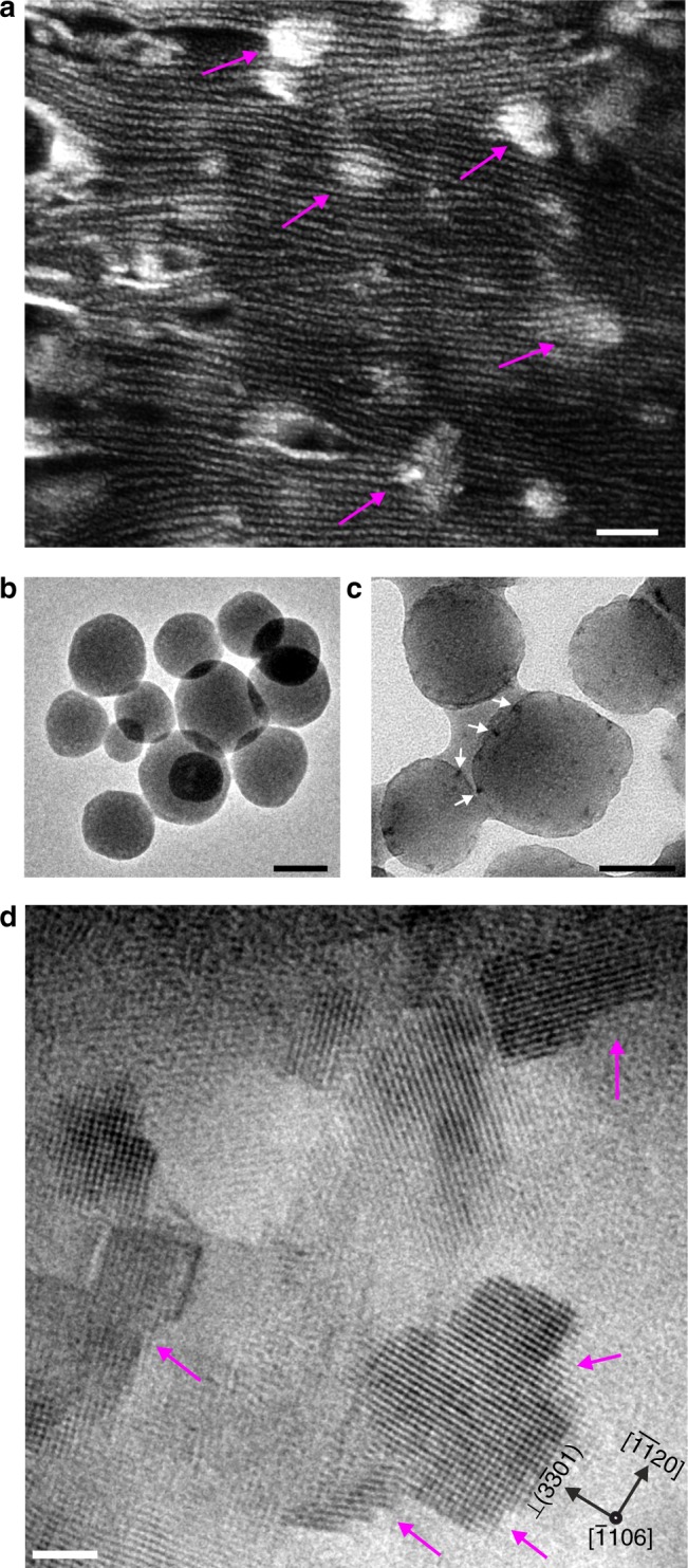
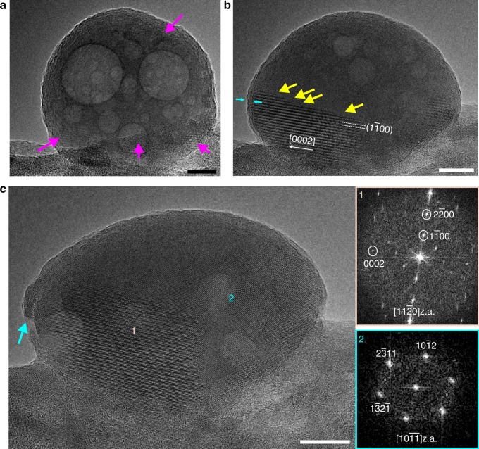
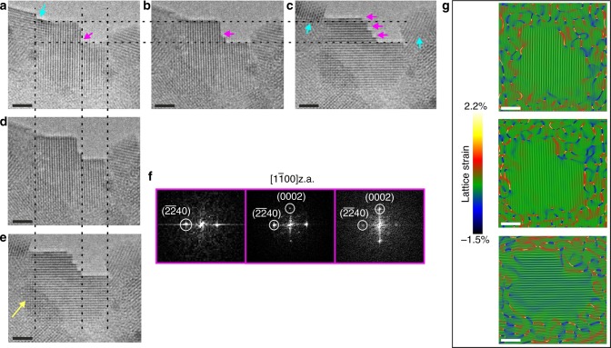
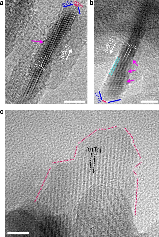
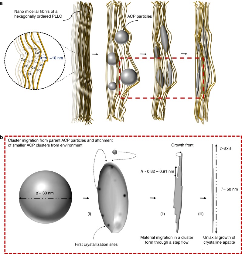
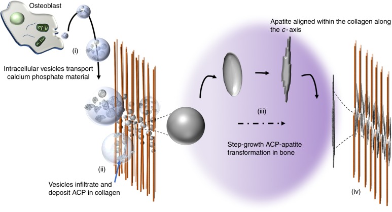
Mineralisation of calcium phosphates in bone has been proposed to proceed via an initial amorphous precursor phase which transforms into nanocrystalline, carbonated hydroxyapatite. While calcium phosphates have been under intense investigation, the exact steps during the crystallisation of spherical amorphous particles to platelet-like bone apatite are unclear. Herein, we demonstrate a detailed transformation mechanism of amorphous calcium phosphate spherical particles to apatite platelet-like crystals, within the confined nanodomains of a bone-inspired nanocomposite. The transformation is initiated under the presence of humidity, where nanocrystalline areas are formed and crystallisation advances via migration of nanometre sized clusters by forming steps at the growth front. We propose that such transformation is a possible crystallisation mechanism and is characteristic of calcium phosphates from a thermodynamic perspective and might be unrelated to the environment. Our observations provide insight into a crucial but unclear stage in bone mineralisation, the origins of the nanostructured, platelet-like bone apatite crystals.


Conflict of interest statement

The authors declare no competing interests.

Figures

Fig. 1
Fig. 1
Morphology of the composite. a SEM image showing the formed ACP particles between the confined domains of the NMFs within the PLLC matrix (arrows). The NMFs appear to be distorted in order to accommodate the large ACP particles. Scale bar, 100 nm. b BF TEM image of freshly formed ACP particles. Scale bar, 50 nm. c BF TEM image of particles that deviate from the spherical morphology as they begin to coalesce. The arrows denote electron dense areas on the particles. Scale bar, 50 nm. d HRTEM image of similar areas denoted in c that correspond to the first crystalline nucleation sites of the crystalline phase. Arrows denote steps edges parallel to 33¯01 and 11¯20 planes. Scale bar, 2 nm
Fig. 2
Fig. 2
Transformation of a partially crystallised ACP particle. a HRTEM image of the ACP particle (arrows denote crystallised domains). b Same particle after 2 min. The crystalline area on the left-hand side has advanced and the growth proceeds via a layer-by-layer mechanism incorporating steps (yellow arrows). The light blue arrows denote a 1.5 nm thick zone around the edges of the particle. c After 4 min, a second crystalline area is observed. The insets correspond to the FFT diffractograms from each area. The  cyan arrow denotes a small crystallite. Aging time of the sample was 3 weeks. Scale bar in all images, 10 nm
Fig. 3
Fig. 3
Step formation at the growth front. a HRTEM image of a small crystallite viewed along the [11¯00].z.a. exhibiting a step (magenta arrow). The edges of the crystallite are diffused. b, d Same crystallite (placed inline and underneath (a)) in which an extra step has been formed. c, e Three steps have been formed. The dashed lines act as a guide for the eye, taking as reference the initial crystallite’s step height and width differences. A ~1–2 ML height difference is visible as well as an increase in the width (denoted by the yellow arrow). Cyan arrows denote the adjacent crystallites that have grown as well. f FFT micrographs, from right to left, obtained from the nanocrystals shown in (a, b and c), respectively. g Bragg filtered images obtained from the respective HRTEM micrographs in (a, b and c) using g = 22¯40 and g = 0002 with their corresponding GPA lattice strain maps superimposed, making the boundaries of the crystallite more apparent. Aging time of the sample was 3 weeks. Scale bar in all images, 2 nm
Fig. 4
Fig. 4
Morphology of aged crystals. a, b HRTEM images of two apatite crystals viewed along the [11¯20]z.a. The magenta arrows denote steps with edges along [0001] and [11¯00]directions. The termination of the apatite crystals is truncated and bounded on the one edge by {011¯1}facets. Cyan dashed lines in b denote a 1.5 nm diffuse area around the crystal. c Side view of an apatite crystal with an irregular shape bounded by facets of various orientations. Scale bar in all images, 5 nm
Fig. 5
Fig. 5
Schematic illustration of the proposed ACP to apatite growth mechanism. a Formation of ACP particles with spherical morphology, which during aging transform to elongated apatite platelets within the PLLC confinements. b Detailed illustration of the growth steps shown in a. (i) The ACP particle starts to deform as several crystalline nuclei are formed within the particle. (ii) Steps are formed as a result of a cluster migration in the particle and the crystal starts to adapt a single orientation. Material that is being moved from the sides of the crystal act as seeds for further growth along the c-axis by a layer-by-layer or cluster incorporation mechanism. (iii) Traces of the steps have been left resulting in crystals with non-uniform thickness
Fig. 6
Fig. 6
Diagram describing a possible bone mineralisation mechanism. Starting from (i), intracellular matrix vesicles bud from osteoblasts and transport ACP precursors as irregular or spherical shaped granules to the gap zones of the collagen matrix (one of the most accepted theories). (ii) The ACP containing vesicles infiltrate the collagen matrix and deposit the ACP granules at the gap zones. (iii) The transformation of the ACP granules into bone apatite along the long-axis of the collagen, via step-flow cluster/ dissolution-growth mechanism. (iv) Fully transformed and matured, mineralised collagen matrix

Similar articles

Cited by

References

    1. Dunlop JWC, Fratzl P. Biological composites. Annu. Rev. Mater. Sci. 2010;40:1–24. doi: 10.1146/annurev-matsci-070909-104421. - DOI
    1. Wegst UGK, Bai H, Saiz E, Tomsia AP, Ritchie RO. Bioinspired structural materials. Nat. Mater. 2015;14:23–36. doi: 10.1038/nmat4089. - DOI - PubMed
    1. Meyers MA, McKittrick J, Chen PY. Structural biological materials: critical mechanics-materials connections. Science. 2013;339:773–779. doi: 10.1126/science.1220854. - DOI - PubMed
    1. Fratzl P, Gupta HS, Paschalis EP, Roschger P. Structure and mechanical quality of the collagen–mineral nano-composite in bone. J. Mater. Chem. 2004;14:2115–2123. doi: 10.1039/B402005G. - DOI
    1. Mahamid J, Sharir A, Addadi L, Weiner S. Amorphous calcium phosphate is a major component of the forming fin bones of zebrafish: Indications for an amorphous precursor phase. Proc. Natl Acad. Sci. USA. 2008;105:12748–12753. doi: 10.1073/pnas.0803354105. - DOI - PMC - PubMed

Publication types