

A Hybrid Finite Volume and Extended Finite Element Method for Hydraulic Fracturing with Cohesive Crack Propagation in Quasi-Brittle Materials
- PMID: 30304867
- PMCID: PMC6213188
- DOI: 10.3390/ma11101921
A Hybrid Finite Volume and Extended Finite Element Method for Hydraulic Fracturing with Cohesive Crack Propagation in Quasi-Brittle Materials
Abstract
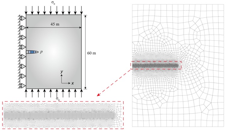
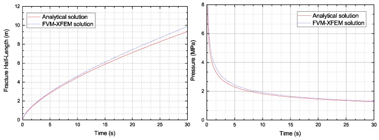
High-pressure hydraulic fractures are often reported in real engineering applications, which occur due to the existence of discontinuities such as cracks, faults, or shear bands. In this paper, a hybrid finite volume and extended finite element method (FVM-XFEM) is developed for simulating hydro-fracture propagation in quasi-brittle materials, in which the coupling between fluids and deformation is considered. Flow within the fracture is modelled using lubrication theory for a one-dimensional laminar flow that obeys the cubic law. The solid deformation is governed by the linear momentum balance equation under quasi-static conditions. The cohesive crack model is used to analyze the non-linear fracture process zone ahead of the crack tip. The discretization of the pressure field is implemented by employing the FVM, while the discretization of the displacement field is accomplished through the use of the XFEM. The final governing equations of a fully coupled hydro-mechanical problem is solved using the Picard iteration method. Finally, the validity of the proposed method is demonstrated through three examples. Moreover, the fluid pressure distribution along the fracture, the fracture mouth width, and the pattern of the fracture are investigated. It is shown that the numerical results correlated well with the theoretical solutions and experimental results.
Keywords: arbitrary crack propagation; extended finite element method (XFEM); finite volume method (FVM); hydraulic fracturing; quasi-brittle materials.
Conflict of interest statement
The authors declare no conflict of interest.
Figures


References
-
- Detournay E. Mechanics of Hydraulic Fractures. Annu. Rev. Fluid Mech. 2016;48:311–339. doi: 10.1146/annurev-fluid-010814-014736. - DOI
-
- Levasseur S., Charlier R., Frieg B., Collin F. Hydro-mechanical modelling of the excavation damaged zone around an underground excavation at Mont Terri Rock Laboratory. Int. J. Rock Mech. Min. 2010;47:414–425. doi: 10.1016/j.ijrmms.2010.01.006. - DOI
-
- Rahm D. Regulating hydraulic fracturing in shale gas plays: The case of Texas. Energy Policy. 2011;39:2974–2981. doi: 10.1016/j.enpol.2011.03.009. - DOI
-
- Adachi J.I., Detournay E. Plane strain propagation of a hydraulic fracture in a permeable rock. Eng. Fract. Mech. 2008;75:4666–4694. doi: 10.1016/j.engfracmech.2008.04.006. - DOI
-
- Perkins T.K., Kern L.R. Widths of hydraulic fractures. J. Pet. Technol. 1961;13:937–949. doi: 10.2118/89-PA. - DOI
Grants and funding
LinkOut - more resources
Full Text Sources
