Review
. 2018 Nov;15(11):771-791.
doi: 10.1080/17434440.2018.1536427. Epub 2018 Oct 29.

Principles of TAVR valve design, modelling, and testing

Affiliations
Review

Principles of TAVR valve design, modelling, and testing

Oren M Rotman et al. Expert Rev Med Devices. 2018 Nov.

Abstract

Introduction: Transcatheter aortic valve replacement (TAVR) has emerged as an effective minimally-invasive alternative to surgical valve replacement in medium- to high-risk, elderly patients with calcific aortic valve disease and severe aortic stenosis. The rapid growth of the TAVR devices market has led to a high variety of designs, each aiming to address persistent complications associated with TAVR valves that may hamper the anticipated expansion of TAVR utility.

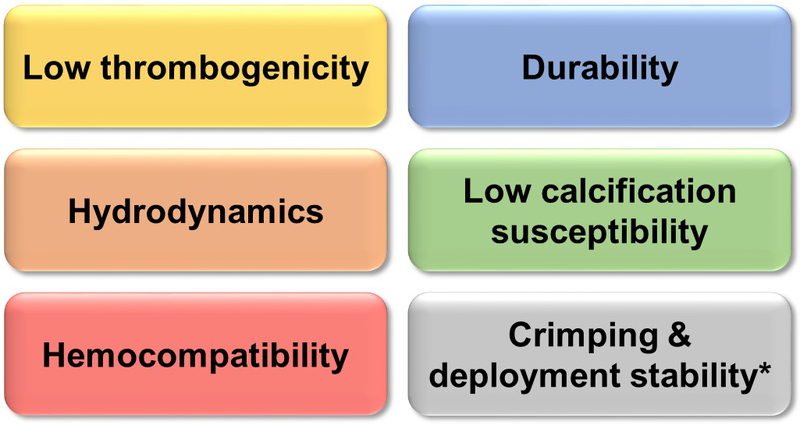
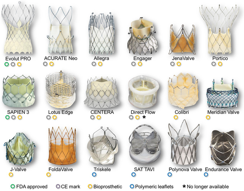
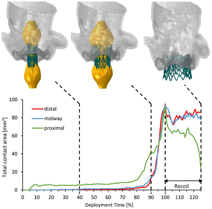
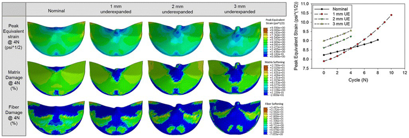
Areas covered: Here we outline the challenges and the technical demands that TAVR devices need to address for achieving the desired expansion, and review design aspects of selected, latest generation, TAVR valves of both clinically-used and investigational devices. We further review in detail some of the up-to-date modeling and testing approaches for TAVR, both computationally and experimentally, and additionally discuss those as complementary approaches to the ISO 5840-3 standard. A comprehensive survey of the prior and up-to-date literature was conducted to cover the most pertaining issues and challenges that TAVR technology faces.

Expert commentary: The expansion of TAVR over SAVR and to new indications seems more promising than ever. With new challenges to come, new TAV design approaches, and materials used, are expected to emerge, and novel testing/modeling methods to be developed.

Keywords: ISO 5840; TAVI; aortic stenosis; calcific aortic valve disease; medical device; prosthetic heart valve; thrombogenicity; valve hydrodynamics.


Conflict of interest statement

Declaration of interest

OM Rotman is a consultant for Polynova Cardiovascular Inc. D Bluestein has stock ownership in Polynova Cardiovascular Inc. The authors have no other relevant affiliations or financial involvement with any organization or entity with a financial interest in or financial conflict with the subject matter or materials discussed in the manuscript apart from those disclosed.

Figures

Figure 1:
Figure 1:
Highlights of a TAVR device key requirements. * The only requirement that is not shared with SAVR devices.
Figure 2:
Figure 2:
Selected TAVR valves based on varying design approaches, both commercially-available and under-investigation devices.
Figure 3:
Figure 3:
Total contact area calculated in the deployment and recoil phases for the distal, midway and proximal configurations. The model in the midway configuration is shown in three instances: 40% and 90% of the deployment time, and at the end of the recoil. Adapted by permission from John Wiley and Sons, Artificial Organs (Bianchi M. et al. Effect of Balloon-Expandable Transcatheter Aortic Valve Replacement Positioning: A Patient-Specific Numerical Model)©2016.
Figure 4:
Figure 4:
Left- Contour plots of the peak equivalent strain and the matrix and fiber damage at the 4th cycle fatigued state for each case. Right- The peak equivalent strain observed in the leaflets for each case and cycle. Reprinted by permission from Springer Nature, Annals of Biomedical Engineering (Martin C. et al. Transcatheter Valve Underexpansion Limits Leaflet Durability: Implications for Valve-in-Valve Procedures)©2016.
Figure 5:
Figure 5:
Post TAVR deployment stresses and strains in SIMULIA beating heart model in close proximity of the AV node (animation freeze frame- Top) - for assessing a mechanical threshold predictive of CCAs (bottom). LHHM – living heart human model; VBB – left bundle branch; MS – membranous septum. (Adapted from Ghosh R.P. et al. P6317Simulation of transcatheter aortic valve performance in a beating heart. European Heart Journal 2018;39(Suppl_1): ehy566.P6317-ehy566.P6317. By permission of Oxford University Press).
Figure 6:
Figure 6:
Example of a Pulse Duplicator (PD) for baseline hydrodynamic testing mitral and aortic valves (Vivitro PD, VivitroLabs, Victoria, BC). (a) mock native aortic root model for deployment of the TAVR device; (b) a typical diagram of transvalvular pressures/flows over a cardiac cycle at CO of 5 l/min. Reprinted by permission from Springer Nature, J Cardiovascular and Translational Research (Rahmani B. et al. In Vitro Hydrodynamic Assessment of a New Transcatheter Heart Valve Concept (the TRISKELE))©2017.
Figure 7:
Figure 7:
PIV setup for eccentric THV deployment. (a) Raw image of the particle laden fluid flow from the imaging plane. Idealized schematic of (b) circular and (c) eccentric deployed TAVRs at peak systole with imaging plane coincident with the lower commissure post and line of coaptation of the lower leaflets. Reprinted by permission from Springer Nature, Annals of Biomedical Engineering (Gunning et al. An in vitro evaluation of the impact of eccentric deployment on transcatheter aortic valve hemodynamics)©2014.
Figure 8:
Figure 8:
Novel platform for hydrodynamic testing in a diseased patient-specific CAVD anatomy. (a) – Vascular Simulations (Stony Brook, NY, USA) upper body arterial Replicator. (b) left – reconstruction of ascending aorta and aortic root based on a CT scan of a patient, based on which aortic root models, shown on the right, were developed. (c) – Corresponding aortic valve models, with (right) or without (left) calcific deposits, (d-e) - the modular valve model (red colored for visibility) fitted into the aorta and left ventricle. Reprinted by permission from Springer Nature, Cardiovascular Engineering and Technology (Rotman O.M. et al. Realistic Vascular Replicator for TAVR Procedures)©2018.
Figure 9:
Figure 9:
Method for optical high spatiotemporal strain analysis for transcatheter aortic valves in-vitro. A – A closed TAVR valve surrounded by the nitinol stent seen from the aortic point of view. The surface of the each leaflet is covered with a fine pattern of ink speckles with a particle size less than 1 μm. The ink is applied directly to the surface of the leaflets by an airbrush. B - Post processing of the experimental data of from the TAVR valve seen by one of two high-speed cameras. The applied facet field is marked by the squares, which each contains a unique signature based on the gray level intensity of the pixels inside it. Using stereophotogrammetry, the facet field is transformed into a three-dimensional surface. To reduce computational time areas with no interest is masked out and no facets were applied. Since the facets need to be visual for both cameras computation of the 3D structure along edges, such as the coaptation lines, is not possible. C - Visualization of the strain distribution of the TAVR valve leaflets on the surface created from digital image correlation. The left column depicts the von Mises strains at varying time points, and the right column depicts the major principal strains. Reprinted from Heide-Jorgensen et al. A Novel Method for Optical High Spatiotemporal Strain Analysis for Transcatheter Aortic Valves In Vitro. Journal of Biomechanical Engineering. 2016 Mar;138(3):4032501. With permission by ASME.
Figure 10:
Figure 10:
(A) Platelet Activity State (PAS) thrombogenicity methodology concept, in which the agonist for platelet activation (here fluid shear) is correlated 1:1 with thrombin formation (Adapted from Bluestein D. et al. Research Approaches for Studying Flow Induced Thromboembolic Complications in Blood Recirculating Devices. Expert Review of Medical Devices 2004;1(1):65-80. With permission by Taylor & Francis Ltd). (B) Implementation of the PAS assay with TAVR valve testing, using a mock left ventricle model and pulsating flow of gel-filtered human platelets in a closed flow loop.

References

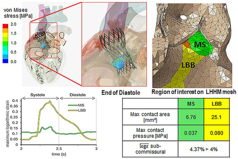
    1. Franzoni I, Latib A, Maisano F, et al. Comparison of incidence and predictors of left bundle branch block after transcatheter aortic valve implantation using the CoreValve versus the Edwards valve. The American journal of cardiology. 2013. August 15;112(4):554–9. doi: 10.1016/j.amjcard.2013.04.026. PubMed PMID: 23726173; eng. - DOI - PubMed
    1. Kurtz CE, Otto CM. Aortic stenosis: clinical aspects of diagnosis and management, with 10 illustrative case reports from a 25-year experience. Medicine. 2010. November;89(6):349–79. doi: 10.1097/MD.0b013e3181fe5648. PubMed PMID: 21057260; eng. - DOI - PubMed
    1. Mohler ER 3rd, Gannon F, Reynolds C, et al. Bone formation and inflammation in cardiac valves. Circulation. 2001. March 20;103(11):1522–8. doi: 10.1161/01.cir.103.11.1522. PubMed PMID: 11257079. - DOI - PubMed
    1. Weinberg EJ, Schoen FJ, Mofrad MR. A computational model of aging and calcification in the aortic heart valve. PloS one. 2009;4(6):e5960. doi: 10.1371/journal.pone.0005960. PubMed PMID: 19536285; PubMed Central PMCID: PMC2693668. - DOI - PMC - PubMed
    1. Rosenhek R, Binder T, Porenta G, et al. Predictors of outcome in severe, asymptomatic aortic stenosis. The New England journal of medicine. 2000. August 31;343(9):611–7. doi: 10.1056/NEJM200008313430903. PubMed PMID: 10965007. - DOI - PubMed

Supplementary concepts

LinkOut - more resources