. 2018 Oct 12;8(10):822.
doi: 10.3390/nano8100822.

Use of Plasma-Synthesized Nano-Catalysts for CO Hydrogenation in Low-Temperature Fischer⁻Tropsch Synthesis: Effect of Catalyst Pre-Treatment

Affiliations

Use of Plasma-Synthesized Nano-Catalysts for CO Hydrogenation in Low-Temperature Fischer⁻Tropsch Synthesis: Effect of Catalyst Pre-Treatment

James Aluha et al. Nanomaterials (Basel). .

Abstract

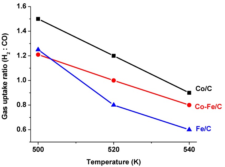
A study was done on the effect of temperature and catalyst pre-treatment on CO hydrogenation over plasma-synthesized catalysts during the Fischer⁻Tropsch synthesis (FTS). Nanometric Co/C, Fe/C, and 50%Co-50%Fe/C catalysts with BET specific surface area of ~80 m² g⁻1 were tested at a 2 MPa pressure and a gas hourly space velocity (GHSV) of 2000 cm³ h-1 g-1 of a catalyst (at STP) in hydrogen-rich FTS feed gas (H₂:CO = 2.2). After pre-treatment in both H₂ and CO, transmission electron microscopy (TEM) showed that the used catalysts shifted from a mono-modal particle-size distribution (mean ~11 nm) to a multi-modal distribution with a substantial increase in the smaller nanoparticles (~5 nm), which was statistically significant. Further characterization was conducted by scanning electron microscopy (SEM with EDX elemental mapping), X-ray diffraction (XRD) and X-ray photoelectron spectroscopy (XPS). The average CO conversion at 500 K was 18% (Co/C), 17% (Fe/C), and 16% (Co-Fe/C); 46%, 37%, and 57% at 520 K; and 85%, 86% and 71% at 540 K respectively. The selectivity of Co/C for C5+ was ~98% with 8% gasoline, 61%, diesel and 28% wax (fractions) at 500 K; 22% gasoline, 50% diesel, and 19% wax at 520 K; and 24% gasoline, 34% diesel, and 11% wax at 540 K, besides CO₂ and CH₄ as by-products. Fe-containing catalysts manifested similar trends, with a poor conformity to the Anderson⁻Schulz⁻Flory (ASF) product distribution.

Keywords: CO-hydrogenation; low-temperature Fischer–Tropsch; nano-catalysts; plasma synthesis; pre-treatment.


Conflict of interest statement

The authors declare no conflict of interest. The funders had no role in the design of the study; in the collection, analyses, or interpretation of data; in the writing of the manuscript, and in the decision to publish the results.

Figures

Figure 1
Figure 1
The activity of (a) Co/C, (b) Fe/C, and (c) Co-Fe/C catalysts tested at 500 K, 520 K, and 540 K (pressure = 2 MPa; GHSV = 2000 cm3 h−1 g−1 of the catalyst) indicating the CO and H2 conversions.
Figure 2
Figure 2
The activity of the Co/C catalyst extended to 72 h on stream at 500 K, 2 MPa and GHSV = 2000 cm3 h−1 g−1 of the catalyst.
Figure 3
Figure 3
The sample pictures showing a massive wax formation in the reactor after an FTS reaction by carbon-supported catalysts that are evidently black with the wax being conspicuously white.
Figure 4
Figure 4
The H2:CO ratio, r, which indicates that all the catalysts, at higher temperatures, converted more CO to form CO2 and probably with increased water-gas shift, FTS demanded less H2.
Figure 5
Figure 5
The selectivity plots of the Co/C catalyst tested at 500 K, 520 K and 540 K, 2 MPa pressure, and GHSV = 2000 cm3 h−1 g−1 of the catalyst.
Figure 6
Figure 6
The aggregated product fractions of the Co/C catalyst tested at 500 K, 520 K, and 540 K (pressure = 2 MPa; GHSV = 2000 cm3 h−1 g−1 of the catalyst).
Figure 7
Figure 7
The aggregate selectivity of (a) Fe/C and (b) Co-Fe/C catalysts tested at 520 K and 540 K (pressure = 2 MPa; GHSV = 2000 cm3 h−1 g−1 of the catalyst).
Figure 8
Figure 8
Modeling the ASF kinetics from selectivity data of the Co/C sample (a) at 500, 520, and 540 K, and (b) at 520 and 540 K.
Figure 9
Figure 9
Modelling ASF kinetics using selectivity data of the (a) Co-Fe/C and (b) single-metal Co/C sample tested at 500 K, and the Fe/C sample tested at 520 K and 540 K.
Figure 10
Figure 10
Plots showing (a) the adsorption-desorption isotherms of the fresh Co-Fe/C sample, and (b) the pore size distribution by the BET surface area analysis.
Figure 11
Figure 11
Sample SEM images of the used catalysts: (i) Co/C (ii) Fe/C and (iii) Co-Fe/C displaying (a) secondary electron images. (b) elemental EDX mapping, and (c) EDX spectra.
Figure 12
Figure 12
The TEM images of the used (a) Co/C (b) Fe/C and (c) Co-Fe/C catalysts with some sections having nanoparticles predominantly below ~5 nm, or ~10 nm, and (d) sections of the Co-Fe/C catalyst with larger nanoparticles ~20 nm and CNFs.
Figure 13
Figure 13
TEM images of the Co-Fe/C catalyst (a) freshly synthesized by plasma, and (b) after pre-treatment in CO, indicating formation of carbon nanofilaments (CNFs).
Figure 14
Figure 14
The particle size analysis by TEM imaging showing (a) a mono-modal nanoparticle distribution in the fresh Co/C catalyst [47]. (b) Bi-modal distribution in the used Co/C. (c) Bi-modal distribution in the Fe/C sample, and (d) multi-modal distribution in the used Co-Fe/C catalyst.
Figure 15
Figure 15
The XPS analysis of the fresh (a) Co/C and (b) Fe/C catalysts. Reproduced with permission from Reference [48]. Copyright Springer, 2018.
Figure 16
Figure 16
The XPS analysis of (a) Co metal, and (b) Fe metal in the fresh Co-Fe/C catalyst samples collected from the main plasma reactor.
Figure 17
Figure 17
The XPS plots quantifying the C-support in the fresh Co-Fe/C catalyst samples collected from (a) the main plasma reactor and (b) the secondary plasma reactor.
Figure 18
Figure 18
The XRD patterns of the catalyst samples for (a) fresh Co/C (b) used Co/C (c) fresh Co-Fe/C, (d) used Co-Fe/C (e) fresh Fe/C and (f) used Fe/C.
Figure 19
Figure 19
The RQA curve fitting of the used (a) Co/C (b) Co-Fe/C, and (c) Fe/C catalyst samples by XRD analysis.

References

    1. Raghubanshi H., Dikio E.D. Synthesis of helical carbon fibers and related materials: A review on the past and recent developments. Nanomaterials. 2015;5:937–968. doi: 10.3390/nano5020937. - DOI - PMC - PubMed
    1. Nasir S., Hussein M.Z., Zainal Z., Yusof N.A. Carbon-based nanomaterials/allotropes: A glimpse of their synthesis, properties and some applications. Materials. 2018;11:295. doi: 10.3390/ma11020295. - DOI - PMC - PubMed
    1. Avouris P., Chen Z., Perebeinos V. Carbon-based electronics. Nat. Nanotechnol. 2007;2:605–615. doi: 10.1038/nnano.2007.300. - DOI - PubMed
    1. Sun X., Suarez A.I.O., Meijerink M., van Deelen T., Ould-Chikh S., Zečević J., de Jong K.P., Kapteijn F., Gascon J. Manufacture of highly loaded silica-supported cobalt Fischer–Tropsch catalysts from a metal organic framework. Nat. Commun. 2017;8:1680. doi: 10.1038/s41467-017-01910-9. - DOI - PMC - PubMed
    1. Zaporotskova I.V., Boroznina N.P., Parkhomenko Y.N., Kozhitov L.V. Carbon nanotubes: Sensor properties. A review. Mod. Electron. Mater. 2016;2:95–105. doi: 10.1016/j.moem.2017.02.002. - DOI