. 2018 Oct 23;9(1):4403.
doi: 10.1038/s41467-018-06895-7.

A microfabricated nerve-on-a-chip platform for rapid assessment of neural conduction in explanted peripheral nerve fibers

Affiliations

A microfabricated nerve-on-a-chip platform for rapid assessment of neural conduction in explanted peripheral nerve fibers

Sandra Gribi et al. Nat Commun. .

Abstract

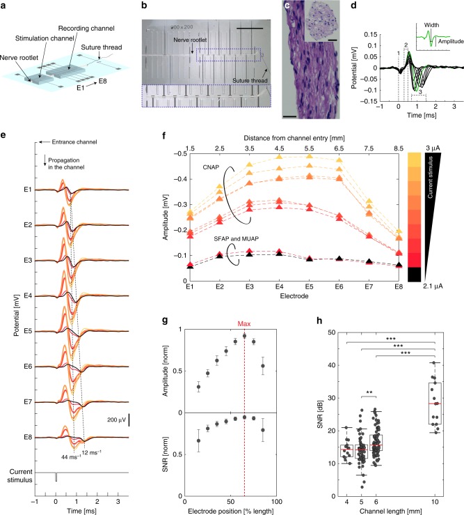
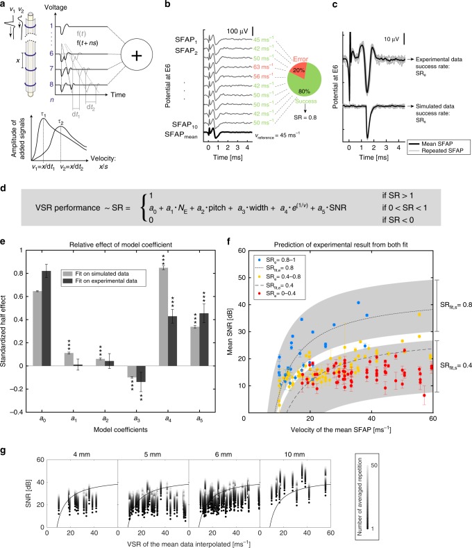
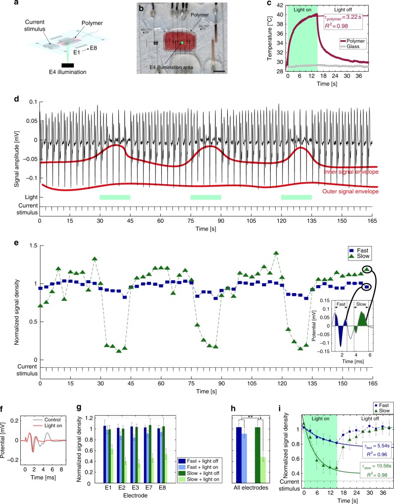
Peripheral nerves are anisotropic and heterogeneous neural tissues. Their complex physiology restricts realistic in vitro models, and high resolution and selective probing of axonal activity. Here, we present a nerve-on-a-chip platform that enables rapid extracellular recording and axonal tracking of action potentials collected from tens of myelinated fibers. The platform consists of microfabricated stimulation and recording microchannel electrode arrays. First, we identify conduction velocities of action potentials traveling through the microchannel and propose a robust data-sorting algorithm using velocity selective recording. We optimize channel geometry and electrode spacing to enhance the algorithm reliability. Second, we demonstrate selective heat-induced neuro-inhibition of peripheral nerve activity upon local illumination of a conjugated polymer (P3HT) blended with a fullerene derivative (PCBM) coated on the floor of the microchannel. We demonstrate the nerve-on-a-chip platform is a versatile tool to optimize the design of implantable peripheral nerve interfaces and test selective neuromodulation techniques ex vivo.


Conflict of interest statement

The authors declare no competing interests.

Figures

Fig. 1
Fig. 1
Nerve-on-a-chip design and recording capabilities. a Schematic of the nerve-on-a-chip platform. b Photographs of a teased nerve rootlet (100 μm diameter) inserted in the platform. Recording and stimulation electrodes are 100 × 300 μm2 and 100 × 600 μm2, respectively; electrode pitch is 1 mm; stimulation and recording microchannels are 8 and 10 mm long respectively. One end of the rootlet is tied with a suture thread then pulled inside the channel, as depicted in a. Scale bar: 5 mm. c Hematoxylin staining of cross and longitudinal section of a rootlet. Scale bar: 25 µm. d Superimposed recording of one SFAP along eight electrodes, highlighting stimulation artifact (label #1, simultaneous on all electrodes), onset artifact provoked by SFAP entry in the recording microchannel (label #2, simultaneous on all electrodes), and biological signals (label #3, depolarization wave, delayed between each electrode) (stimulation current: 2.1 µA, phase: 50 µs). Insert: SFAP amplitude is measured from baseline and SFAP width is measured at half amplitude. e Representative nerve signals recorded along one rootlet by all eight electrodes with increasing stimulation current (increment: 0.1 µA). Recorded signals are either SFAP, MUAP, or CAP. Color from black to yellow: stimulation current from 2.1 to 3 μA (increment: 0.1 μA, phase: 50 µs). f Maximal amplitude of neural signals along the channel. Increasing current pulses trigger SFAP, MUAP, then CAP (color code as in e and f). g Average of normalized SFAP amplitude and SNR along all eight electrodes. Maximal SNR and amplitude is reached at 2/3 of the microchannel length (red dashed line). Error bar: pooled standard error (n = 14 SFAP, each repeated 10 × ). h Boxplots of SFAP SNR recorded in microchannel. SNR is positively correlated with velocity (Supplementary Fig. 3); resulting SNR range increases with microchannel length. Pair comparison was done using Kruskal–Wallis test (α = 0.05) with Bonferroni correction (4 mm: n = 22, 5 mm: n = 75, 6 mm, n = 86 10 mm: n = 16). Significance: ***p < 0.001, **p < 0.01
Fig. 2
Fig. 2
Prediction of VSR algorithm performance. a VSR principle, adapted from. SFAP are traveling along the nerve recorded by n electrodes spaced by x (gray line). The recordings on each electrode are shifted by ns (black line), where s corresponds to the propagation delay between two electrodes (multiple of the sampling frequency). For each value of s, all recordings are summed. The sum becomes constructive when s matches dt (alignment of propagating SFAP). b Example of calculation of the SR. Each simulated or recorded SFAP is elicited 10 times and averaged. The SR is the proportion of SFAP with a calculated velocity equal to the velocity of the mean SFAP (see Eq. 1). c Example of recorded SFAP repetitions and mean (experimental data) and its simulated version (amplitude = 55 µV, SNR = 30 dB, width = 0.22 ms, and velocity = 13.3 ms–1). d Linear model resulting from preliminary simulation (see Supplementary Methods). The model terms are function of the number of electrode (NE), the electrode pitch (pitch), the SFAP width at half prominence (width), the SFAP velocity (e1/v) and the maximum SNR along the channel (SNR). The model coefficients ai were fitted to experimental and simulated data. e Relative effect of each model terms on the SR. Model coefficients, expressed as standardized half effect, were computed from simulated and experimental data. Error bar: 95% confidence interval. Significance (ANOVA, α = 0.05, Supplementary Methods 3): ***p < 0.001, **p < 0.01. f Experimental SR (SRe), as well as SR predictions from our model fitted on experimental (SRfit,e, dashed line, for width = 0.03 ms, NE and pitch: n/a) and simulated data (SRfit,s, gray area, width = 0.03, NE = 3-8, pitch = 1.33–0.67 mm). Error bar: standard deviation (n = 10). g SR as a result of SNR, velocity and channel length. Black dot shows experimental results and lighter dots show the calculated increase of SNR in function of signal averaging. The black line (SRe = 0.8) delimits the region for “safe” velocity calculation (above line)
Fig. 3
Fig. 3
Heat-induced neuroinhibition. a, b Schematic and photograph of the nerve-on-a-chip integrating a thin film of P3HT:PCBM on the floor of the channel (red). Illumination is focused on electrode E4. Scale bar: 5 mm. c Temperature during illumination. A 15-s light pulse was applied through the polymer and bare glass. The temperature changed with a time constant of 3.22 s (Supplementary Equation 13). d Close-up of a rootlet concatenated recording captured downstream the illumination area (electrode E7). Every 3-s MUAP were elicited with a current pulse. Variation in signal envelope shows reduction of the signal amplitude. e NSD of slow and fast fibers corresponding to the recording in d. Box: a representative MUAP; the fast and slow signals were integrated to calculate their corresponding NSD. Each NSD was then normalized with its control response (10 first elicited MUAP). f MUAP captured by electrode E7 and averaged across light pulses. g NSD average across all four rootlets, repeated stimulation (3 × ) and light treatment at each Pt electrodes (3 × heating/cooling cycle). Right-panel: additional average across Pt electrodes are shown in the right-panel. Error bars: pooled standard error (n = 4, each repeated 9 × ). h Additional average from data in g across Pt electrodes. Error bars: pooled standard error (n = 4, each repeated 45 × ). A four-way ANOVA was performed (α = 0.05, Supplementary Methods). The illumination effect is significant, as well as the difference of inhibition between fast and slow fibers, meaning that the effect of the illumination was stronger on slow fibers than on fast fibers. Post-hoc one-way ANOVA (α = 0.05, Supplementary Methods) applied on slow and fast fiber separately showed a significant effect of the illumination on slow but not on fast fiber. Significance: **p < 0.01, *p < 0.05. i Kinetics of inhibition of slow and fast fiber averaged across light pulses, Pt electrodes and rootlets. Exponential fit (Supplementary Equations 15-16) highlights a higher time constant for slow fiber than for fast fiber. Error bars: pooled standard error (n = 4, each repeated 60 × ). R2 R-squared of the fit

Similar articles

Cited by

References

    1. Hodgkin A. L., Huxley A. F. The dual effect of membrane potential on sodium conductance in the giant axon ofLoligo. The Journal of Physiology. 1952;116(4):497–506. doi: 10.1113/jphysiol.1952.sp004719. - DOI - PMC - PubMed
    1. Dragas J, et al. A multi-functional microelectrode array featuring 59760 electrodes, 2048 electrophysiology channels, stimulation, impedance measurement and neurotransmitter detection channels. IEEE J. Solid-State Circuits. 2017;52:1576–1590. doi: 10.1109/JSSC.2017.2686580. - DOI - PMC - PubMed
    1. Egert Ulrich, Heck D, Aertsen A. Two-dimensional monitoring of spiking networks in acute brain slices. Exp. Brain Res. 2002;142:268–274. doi: 10.1007/s00221-001-0932-5. - DOI - PubMed
    1. Feyen P, et al. Light-evoked hyperpolarization and silencing of neurons by conjugated polymers. Sci. Rep. 2016;6:srep22718. doi: 10.1038/srep22718. - DOI - PMC - PubMed
    1. Petersen CCH. Whole-cell recording of neuronal membrane potential during behavior. Neuron. 2017;95:1266–1281. doi: 10.1016/j.neuron.2017.06.049. - DOI - PubMed

Publication types