. 2018 Oct 24;18(11):3614.
doi: 10.3390/s18113614.

A Non-Linear Model of an All-Elastomer, in-Plane, Capacitive, Tactile Sensor Under the Application of Normal Forces

Affiliations

A Non-Linear Model of an All-Elastomer, in-Plane, Capacitive, Tactile Sensor Under the Application of Normal Forces

Kourosh M Kalayeh et al. Sensors (Basel). .

Abstract

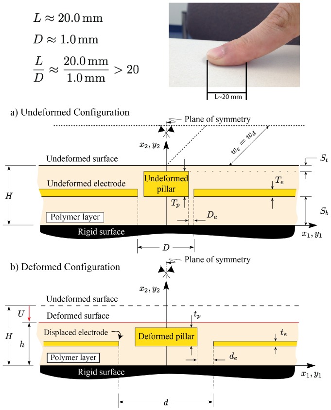
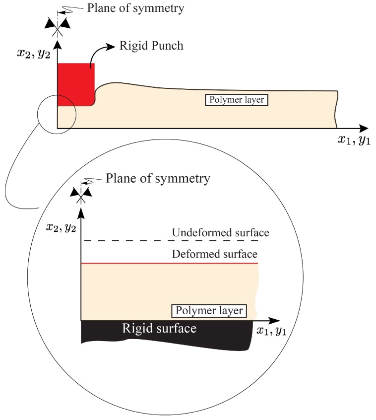
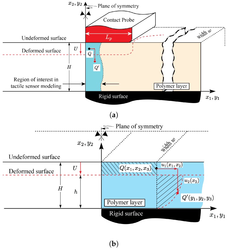
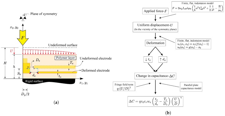
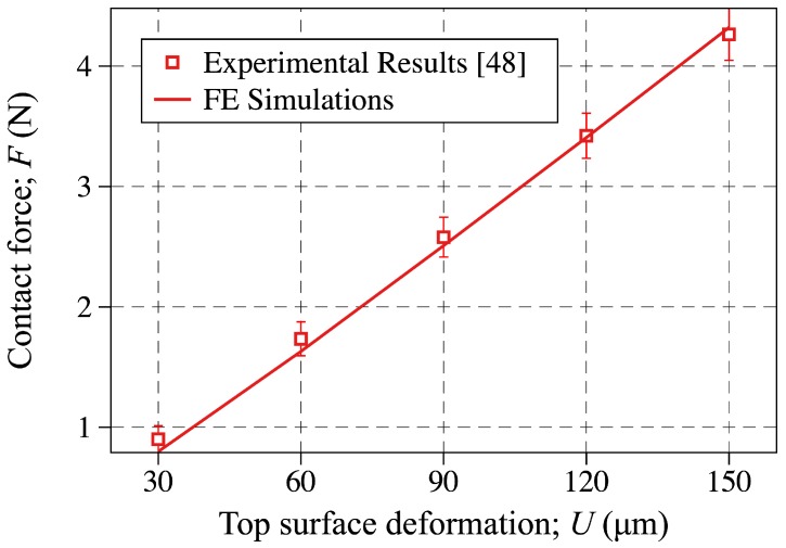
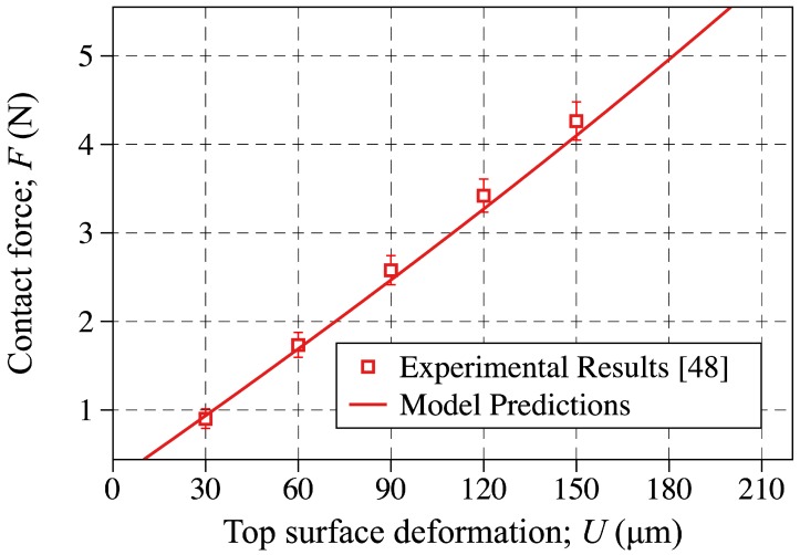
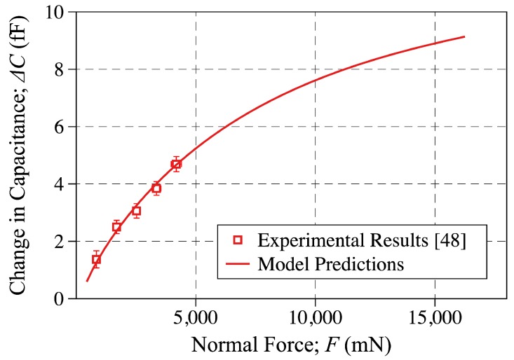
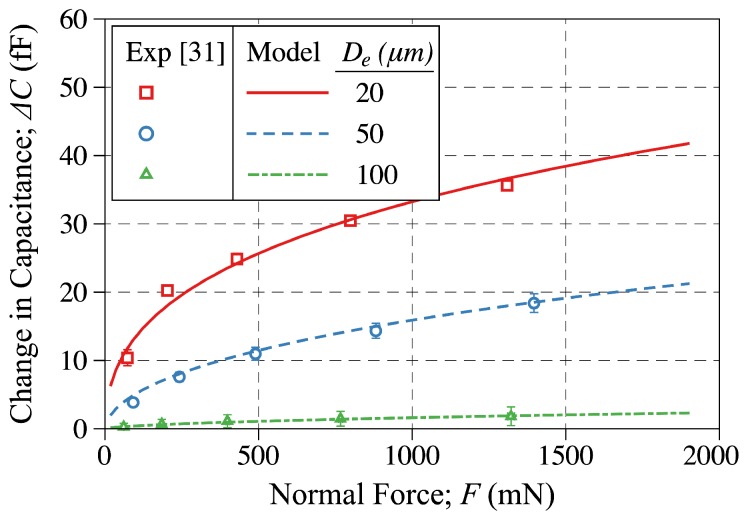
In this work, a large deformation, non-linear semi-analytical model for an all-elastomer, capacitive tactile unit-sensor is developed. The model is capable of predicting the response of such sensors over their entire sensing range under the application of normal forces. In doing so the finite flat punch indentation model developed earlier is integrated with a capacitance model to predict the change-in-capacitance as a function of applied normal forces. The empirical change-in-capacitance expression, based on the parallel plate capacitance model, is developed to account for the fringe field and saturation effects. The elastomeric layer used as a substrate in these sensors is modeled as an incompressible, non-linear, hyperelastic material. More specifically, the two term Mooney-Rivlin strain energy function is used as a constitutive response to relate the stresses and strains. The developed model assumes both geometrical as well as material non-linearity. Based on the related experimental work presented elsewhere, the inverse analysis, combining finite element (FE) modeling and non-linear optimization, is used to obtain the Mooney-Rivlin material parameters. Finally, to validate the model developed herein the model predictions are compared to the experimental results obtained elsewhere for four different tactile sensors. Great agreements are found to exist between the two which shows the model capabilities in capturing the response of these sensors. The model and methodologies developed in this work, may also help advancing bio-material studies in the determination of biological tissue properties.

Keywords: analytical modeling; capacitive all-elastomer tactile sensors; finite elements; finite flat punch indentation; inverse analysis.


Conflict of interest statement

The authors declare no conflict of interest.

Figures

Figure 1
Figure 1
A schematic of the tactile unit-sensor designed and fabricated in [48]. Undeformed (reference) configuration is shown in (a); while the deformed (current) configuration is shown in (b). Due to typical large contact length-electrode spacing ratios, the mechanics of the elastomeric layer in the vicinity of the symmetry plane can be modeled as uniform compression of an infinitely long layer.
Figure 2
Figure 2
A schematic of an infinitely long elastomeric layer compressed by a finite flat punch. The schematic corresponding to the uniform compression can be seen as a close-up view of the indentation model in the vicinity of the symmetry plane.
Figure 3
Figure 3
(a) A schematic of a boundary value problem associated with the finite flat indentation case. The region of interest in the tactile sensor modeling, in the vicinity of the symmetry plane, is highlighted; (b) Magnified view of the highlighted region in (a) which can be modeled as the uniform compression case. For clarity, the conductive features are not shown.
Figure 4
Figure 4
(a) A schematic of the half symmetric cross section of the tactile sensor designed and fabricated in [48] and modeled in this study; (b) A flowchart showing the process used in this study to model the relationship between the change-in-capacitance and applied force.
Figure 5
Figure 5
A detailed geometry of the tactile unit-sensor designed and fabricated in [48].
Figure 6
Figure 6
(a) The domain and associated boundary conditions used in carrying out the FE simulations; (b) The typical mesh used in FE analysis.
Figure 7
Figure 7
A flowchart of inverse FE optimization used in estimating the Mooney-Rivlin material parameters.
Figure 8
Figure 8
The objective function given by Equation (16) evaluated and plotted against the number of iterations to show the convergence behavior of the inverse problem employed in this study to find the M-R material parameters.
Figure 9
Figure 9
Probe contact force plotted against the top surface deformation obtained through experimental results reported in [48] (discrete points) and FE simulations carried out in this study (solid line). In obtaining the FE simulations the M-R material parameters obtained via the inverse analysis are used.
Figure 10
Figure 10
The probe contact force plotted against the top surface deformation level. The discrete points are showing the experimental result reported in [48], whereas the solid line is showing the modeling results obtained through Equation (10).
Figure 11
Figure 11
The change-in-capacitance plotted against the applied force. The discrete points are showing the experimental measurements reported in [48], while the solid line is showing the modeling results obtained in this study. The model predictions are reported for q=0.2469 and γ=0.2720.
Figure 12
Figure 12
The change-in-capacitance plotted against the applied force. The discrete points are showing the experimental measurements reported in [31], while the solid line is showing the modeling results obtained in this study. The model predictions are reported for q=2.52, 2.10, 0.42 and γ=0.27, 0.07, 0.13 for electrode gaps of De=20, 50, and 100 μm, respectively.
Figure 13
Figure 13
The electrode (a) thickness and (b) spacing plotted against the applied force. The results are obtained using the model developed in this study i.e., Equations (13) and (14).

References

    1. Zou L., Ge C., Wang Z.J., Cretu E., Li X. Novel Tactile Sensor Technology and Smart Tactile Sensing Systems: A Review. Sensors. 2017;17:2653. doi: 10.3390/s17112653. - DOI - PMC - PubMed
    1. Chi C., Sun X., Xue N., Li T., Liu C. Recent Progress in Technologies for Tactile Sensors. Sensors. 2018;18:948. doi: 10.3390/s18040948. - DOI - PMC - PubMed
    1. Yogeswaran N., Dang W., Navaraj W., Shakthivel D., Khan S., Polat E., Gupta S., Heidari H., Kaboli M., Lorenzelli L., et al. New materials and advances in making electronic skin for interactive robots. Adv. Robot. 2015;29:1359–1373. doi: 10.1080/01691864.2015.1095653. - DOI
    1. Watanabe K., Sohgawa M., Kanashima T., Okuyama M., Norna H. Identification of various kinds of papers using multi-axial tactile sensor with micro-cantilevers; Proceedings of the 2013 World Haptics Conference (WHC); Daejeon, Korea. 14–18 April 2013.
    1. Xu D., Loeb G.E., Fishel J.A. Tactile identification of objects using Bayesian exploration; Proceedings of the 2013 IEEE International Conference on Robotics and Automation; Karlsruhe, Germany. 6–10 May 2013.

LinkOut - more resources