Review
. 2018 Aug 1;5(10):1700931.
doi: 10.1002/advs.201700931. eCollection 2018 Oct.

Blending Electronics with the Human Body: A Pathway toward a Cybernetic Future

Affiliations
Review

Blending Electronics with the Human Body: A Pathway toward a Cybernetic Future

Mehdi Mehrali et al. Adv Sci (Weinh). .

Abstract

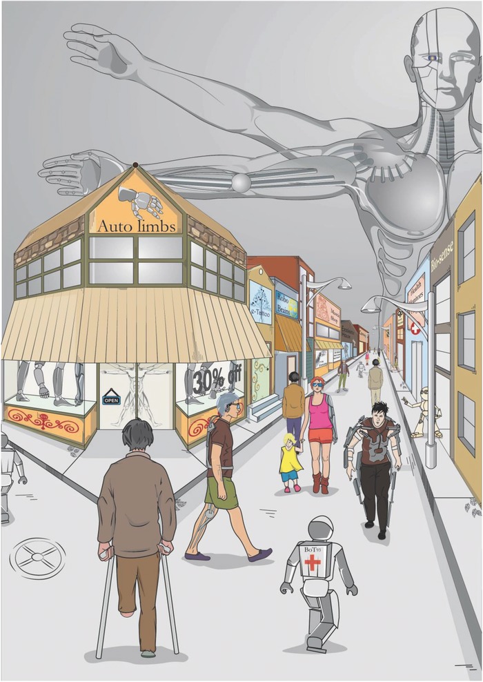
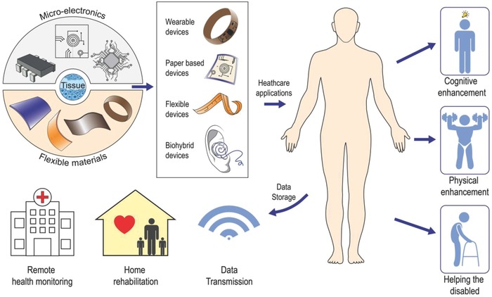
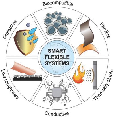
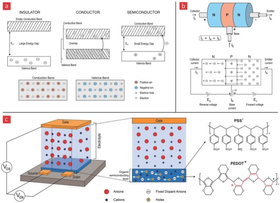
At the crossroads of chemistry, electronics, mechanical engineering, polymer science, biology, tissue engineering, computer science, and materials science, electrical devices are currently being engineered that blend directly within organs and tissues. These sophisticated devices are mediators, recorders, and stimulators of electricity with the capacity to monitor important electrophysiological events, replace disabled body parts, or even stimulate tissues to overcome their current limitations. They are therefore capable of leading humanity forward into the age of cyborgs, a time in which human biology can be hacked at will to yield beings with abilities beyond their natural capabilities. The resulting advances have been made possible by the emergence of conformal and soft electronic materials that can readily integrate with the curvilinear, dynamic, delicate, and flexible human body. This article discusses the recent rapid pace of development in the field of cybernetics with special emphasis on the important role that flexible and electrically active materials have played therein.

Keywords: conductive polymers; cyborganics; flexible bioelectronics; nanomaterials; wearable healthcare monitors.


Figures

Figure 1
Figure 1
Recent innovations in materials science are leading humanity on the road to a cybernetic future—a future wherein, the fine‐line between machine and human will slowly fade away and pave the way for cyborg‐like humans.
Figure 2
Figure 2
The union of microelectronics, flexible materials, and living tissues has led to a great variety of cybernetic devices that can bring relief to the lives of those disabled from disease or aging, enhance the physical capabilities of human beings beyond normality, and expand human consciousness toward uncharted territories.
Figure 3
Figure 3
Special materials with special properties are required for proper interfacing between the electrical and biological components of cybernetic devices.
Figure 4
Figure 4
Energy bands and semiconductor‐related devices. a) Energy‐band diagrams for insulators, conductors, and semiconductors. The current in semiconductors are either generated from electrons (−) or electron holes (+). b) A transistor is basically made from three different semiconductors. The current can only run in one direction in a transistor, and the current that passes through it is typically enhanced with a sustainable gain factor, making them suitable for various sensing applications. c) A qualitative illustration of the working principles behind a sensor that is based on a field‐effect transistor made from PEDOT:PSS, which is an organic semiconductor capable of absorbing electrolytes (anions) from a solution. The uptake of anions abolishes the mobile holes within PEDOT:PSS and thus changes the current that passes through it; it thereby enables it to sense biological processes that either diminish or increase the amount of electrolytes in the surrounding environment.
Figure 5
Figure 5
Various a) manufacturing methods of graphene. Reproduced with permission.447 Copyright 2012, Nature Publishing Group, b) graphene oxide, reduce graphene oxide, and graphene oxide nanosheets are highlighted here. c) Graphene contains numerous functionalities, which can be used to firmly attach it to the backbone of polymers.
Figure 6
Figure 6
Various CNT a) production and b) functionalization strategies. c) A self‐healing and flexible PVA‐CNT based composite for human motion detection. Adapted with permission.196 Copyright 2017, Wiley‐VCH.
Figure 7
Figure 7
Gallium oxide, its properties, and application in flexible bioelectronics. a) The chemical structure of gallium oxide. b) The many unique properties that gallium oxide has to offer. c) Incorporation into polymers to yield flexible and electrical circuits. d) A gallium embedded PDMS substrate with high‐fidelity and stretchable circuits. Reproduced with permission.272 Copyright 2013, Wiley‐VCH.
Figure 8
Figure 8
The field of patient empowerment is currently driven by wearable healthcare monitors (e.g., smart bandages, electronic skin devices, tattoo‐based sensors) and implantable monitors (e.g., flexible electrodes for electrocardiography [ECG] and smart stents for angioplasty). Made by Harder&Muller.
Figure 9
Figure 9
An e‐skin device for monitoring melanoma and skin lesions. a) The device was fabricated through a layer‐by‐layer assembly of Pt/Au electrodes, a piezoelectric component, and a soft and biocompatible PI‐based polymer interfacing the device with the human skin. b) A bright‐field image of the generated e‐skin device. Mechanical mapping of various skin pathologies located c) below the breast, d) on the leg, e) around the nose, f) on the forehead, g) close to the eye, and h) on the neck. Adapted with permission.289 Copyright 2015, Macmillan Publishers Ltd.
Figure 10
Figure 10
A flexible ear electrode for brain–machine interfacing. a) Schematic illustration of the electrode and the principles underlying the EEG monitoring. b) Images showing the electrode and its mounting on the ear. c) Finitive element method (FEM) analysis of the strain on the device upon mechanical bending (180°). d) EEG alpha wave recordings were fairly stable for up to 14 days after mounting the ear electrode on the user. Adapted with permission.347 Copyright 2015, National Academy of Sciences.
Figure 11
Figure 11
Engineering of an intracranial stent‐electrode (stentrode) array for recording brain activity. a) Preimplant Images showing the presence of intracranial lumens (blue arrow) and cortical veins (red arrow). b) Images showing the self‐expanding property of the stentrode. c) The integration of the stentrode within blood vessels of a sheep brain. The yellow arrows correspond to the electrodes, while the green arrows correspond to the delivery cathers. d,e) The stentrode was able to record high‐fidelity signals following the implantation. The recorded peak‐to‐peak amplitude was fairly stable for up to 28 days. f) Recordings of somatosensory evoked potential (SSEP). g) The position of the implanted stentrode in four different sheep models. h) A 3D representation of an implanted stentrode and its corresponding peak‐to‐peak amplitude recording. Adapted with permission.391 Copyright 2016, Macmillan Publishers Ltd.
Figure 12
Figure 12
A depiction of some of the most noteworthy cybernetic prosthetics that we anticipate will spearhead the coming cybernetic revolution. Made by Harder&Muller.
Figure 13
Figure 13
Neural implants with native‐like elasticity. a) Schematics of the electronic dura (e‐Dura) mater implant and how it works in vivo. b) The elastic properties of e‐Dura and various native tissues. c) Postimplantation walking efficiency of rats, the circularity index of the operated spinal cord after 6 weeks, and the density of two cellular markers for foreign body response (astrocytes & microglia) in the spinal‐cord. d) The local longitudinal strain of the e‐Dura increased by much more as a function of applied strain as compared to a conventional rigid implant. This is indicative of a more compliant implant that can cope with the movement of the spinal‐cord region during daily activities. Adapted with permission.15 Copyright 2015, AAAS.
Figure 14
Figure 14
Self‐powered brain–machine interfaces. a) Schematics of the piezoelectric energy harvester and photographs showing the device in its original, bending, and release state. b) The electrical signal measured from the device during bending and unbending in the forward connection and c) reverse connection. d) Depiction of the animal experiment, and data related to the stimulation of paw movement of mice through bending and unbending of the flexible energy harvester. Adapted with permission.404 Copyright 2015, the Royal Society of Chemistry.
Figure 15
Figure 15
Syringe‐injectable electronics for neural recording. a) Depictions of syringe‐injectable electronics. b) Schematics showing the injection of the electronics into the brain of mice. c) Photographs depicting the injection process into a three‐month‐old mouse brain. d,e) Schematics showing the areas of the mice brain, wherein the mesh electronics was injected. f) Bright‐field microscopy imaging of the brain region into which the mesh electronics was injected five weeks after injection. g) Bright‐field and epi‐fluorescence images corresponding to the region indicated by a white box in (f). h) Fluorescence image corresponding to the region indicated by a blue box in (f). i,j) Electrical recordings from the mouse brain using the injected mesh electronics. Adapted with permission.409 Copyright 2015, Macmillan Publishers Ltd.
Figure 16
Figure 16
A cyborg ear for enhanced auditory sensing. a,b) Schematics showing the 3D printing of the artificial ear. c) Photographs of the printed ear before and after culturing. d) Chrondogenic cell viability and secretion of important chrondogenic markers. e) Audio signals were transmitted through the right ear (R) and received through the left ear (L) with good fidelity. Adapted with permission428 Copyright 2013, American Chemical Society.

References

    1. Klugman C. M., Lit. Med. 2001, 20, 39. - PubMed
    1. Wang S., Chinnasamy T., Lifson M. A., Inci F., Demirci U., Trends Biotechnol. 2016, 34, 909. - PMC - PubMed
    1. Kim D. H., Ghaffari R., Lu N., Rogers J. A., Annu. Rev. Biomed. Eng. 2012, 14, 113. - PubMed
    1. Piwek L., Ellis D. A., Andrews S., Joinson A., PLoS Med. 2016, 13, e1001953. - PMC - PubMed
    1. Demetriou M. D., Launey M. E., Garrett G., Schramm J. P., Hofmann D. C., Johnson W. L., Ritchie R. O., Nat. Mater. 2011, 10, 123. - PubMed

LinkOut - more resources