. 2018 Oct 30;8(1):16040.
doi: 10.1038/s41598-018-34271-4.

Injection locking of multiple auto-oscillation modes in a tapered nanowire spin Hall oscillator

Affiliations

Injection locking of multiple auto-oscillation modes in a tapered nanowire spin Hall oscillator

Kai Wagner et al. Sci Rep. .

Abstract

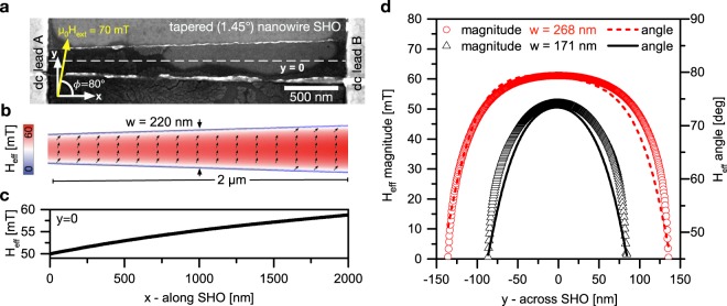
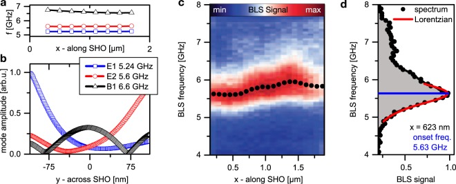
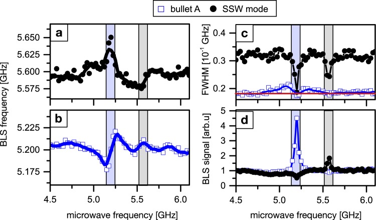
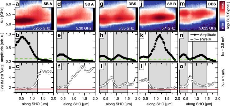
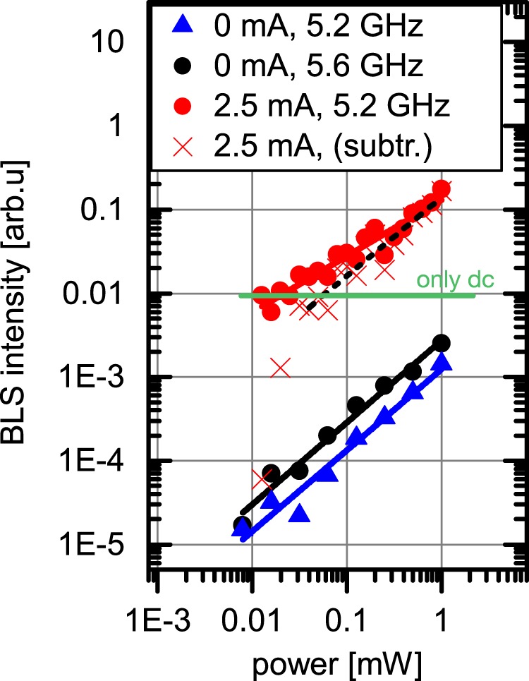
Spin Hall oscillators (SHO) are promising candidates for the generation, detection and amplification of high frequency signals, that are tunable through a wide range of operating frequencies. They offer to be read out electrically, magnetically and optically in combination with a simple bilayer design. Here, we experimentally study the spatial dependence and spectral properties of auto-oscillations in SHO devices based on Pt(7 nm)/Ni80Fe20(5 nm) tapered nanowires. Using Brillouin light scattering microscopy, we observe two individual self-localized spin-wave bullets that oscillate at two distinct frequencies (5.2 GHz and 5.45 GHz) and are localized at different positions separated by about 750 nm within the SHO. This state of a tapered SHO has been predicted by a Ginzburg-Landau auto-oscillator model, but not yet been directly confirmed experimentally. We demonstrate that the observed bullets can be individually synchronized to external microwave signals, leading to a frequency entrainment, linewidth reduction and increase in oscillation amplitude for the bullet that is selected by the microwave frequency. At the same time, the amplitude of other parasitic modes decreases, which promotes the single-mode operation of the SHO. Finally, the synchronization of the spin-wave bullets is studied as a function of the microwave power. We believe that our findings promote the realization of extended spin Hall oscillators accomodating several distinct spin-wave bullets, that jointly cover an extended range of tunability.


Conflict of interest statement

The authors declare no competing interests.

Figures

Figure 1
Figure 1
Samples. (a) SEM micrograph of the tapered nanowire SHO. (b) Micromagnetic simulation of the effective field for an external magnetic field of 70 mT applied under an angle ϕ = 80° with respect to the long axis of the SHO (x-axis). The magnitude is color coded, arrows indicate the orientation of the effective field and magnetization. (c) Simulated magnitude of the effective field along the SHO (x-axis) extracted in the centre of the nanowire (y = 0). (d) Simulated effective field distribution across the nanowire (y-axis) for both ends of the active region.
Figure 2
Figure 2
Linear spin-wave modes of the SHO. (a) Mode frequencies along the SHO (x-direction) as determined from micromagnetic simulations of the local spin-wave spectrum. (b) Simulated mode amplitude profile in the center of the SHO (plotted against y-direction) for the three resonances. (c) Thermal BLS microscopy measurements. Each vertical line represents a spectrum for a fixed position on the SHO with the intensity color coded. The dots indicate the onset frequencies of the spin-wave band that are determined via Lorentzian fits, as is exemplarily shown in (d) for the spectrum recorded at x = 623 nm.
Figure 3
Figure 3
Auto-oscillatory modes. (a) Measured BLS intensity (black dots) integrated over four equidistant x-positions and inverse intensity (blue triangles). The output power calculated according to an analytical approximation (solid and dashed lines) agrees well with the experimental data when assuming a critical current ζ = 2.28 mA, nonlinear coefficient Q = 0.8 and noise η = 1. (b) BLS spectra recorded for Idc = 2.5 mA along the SHO with the intensity color coded on a logarithmic scale. Two regions of pronounced intensity and different frequency are observed at x = 480 nm and x = 1250 nm. (c) Two exemplary BLS spectra measured at different positions for Idc = 2.5 mA. A low-frequency (LF), middle-frequency (MF) and high-frequency (HF) peak can be distinguished and fitted by Lorentzian functions. (d,e) Amplitude distribution and local frequency of the LF, MF, and HF peak along the SHO (x-axis). The black line in (d) shows the amplitude distribution of the auto-oscillating mode according to the proposed formation of two spin-wave bullets.
Figure 4
Figure 4
Injection locking of the SHO. Microwave frequencies are applied in the range between 4.5 and 6.2 GHz at a nominal ac output power of 0.06 mW and a driving current of Idc = 2.5 mA. Measurement position on bullet A at x = 500 nm. The frequencies (a,b), amplitudes (c) and FWHM (d) are shown for bullet A (blue hollow squares) and the SSW mode (black dots). The black and blue solid lines serve as a guide to the eye. The estimated locking intervals of about 100 MHz width centered around the auto-oscillation frequencies of 5.2 and 5.57 GHz are marked by light-blue and grey boxes, respectively. Within these windows, frequency locking, amplitude enhancement/suppression, and linewidth reduction (detection limit marked by a red line in c) are observed.
Figure 5
Figure 5
Spatial distribution of amplitude and linewidth during injection locking. Microwave frequencies of 5.255 GHz (ac), 5.3 GHz (df), 5.35 GHz (gi), 5.4 GHz (jl) and 5.625 GHz (km) are applied with a nominal ac power of 1 mW and a driving current of Idc = 2.5 mA. (a,d,g,j,m) Spatially resolved BLS measurements. (b,e,h,k,n) local amplitude of the auto-oscillation signal and its FWHM (c,f,i,l,o) as determined from Lorentzian fitting of each spectra. For different frequencies of the injected microwave signal, locking of either only one bullet (SB A for locked bullet A, SB B for locked bullet B) or two spatially separated regions (DBS) is observed. In the locked regions, the linewidth is reduced accompanied by an increase in oscillation amplitude. In addition, the maximum amplitude of the free-running auto-oscillation (green dashed line) and spectral resolution of the BLS microscope (red line) is indicated.
Figure 6
Figure 6
Auto-oscillation intensity as a function of the injected microwave power in the locked regime for Idc = 2.5 mA. The signal amplitude measured on the position of bullet A for x = 500 nm and and a microwave frequency of 5.2 GHz is shown as red dots. Linear fitting of the data suggests a power law with an exponent of 0.67 (red line). For comparison the recorded BLS intensity without an externally applied signal is shown as a green horizontal line. The signal amplitude subtracted by this base-intensity is additionally shown as red crosses. Blue triangles and black squares give the amplitude of the directly excited magnetization dynamic by the rf current when the SHO is turned off (Idc = 0) for microwave frequencies of 5.2 GHz and 5.6 GHz, respectively.

References

    1. Locatelli N, Cros V, Grollier J. Spin-torque building blocks. Nat. Publ. Group. 2014;13:11–20. - PubMed
    1. Miwa S, et al. Highly sensitive nanoscale spin-torque diode. Nat. Mater. 2014;13:50–56. doi: 10.1038/nmat3778. - DOI - PubMed
    1. Choi HS, et al. Spin nano–oscillator–based wireless communication. Sci. Reports. 2014;4:1488. - PMC - PubMed
    1. Urazhdin S, et al. Nanomagnonic devices based on the spin-transfer torque. Nat. Nanotechnol. 2014;9:509–513. doi: 10.1038/nnano.2014.88. - DOI - PubMed
    1. Slavin A. Microwave sources: Spin-torque oscillators get in phase. Nat. Nanotechnol. 2009;4:479–480. doi: 10.1038/nnano.2009.213. - DOI - PubMed