

doi: 10.3389/fncir.2018.00088.
eCollection 2018.
VAST (Volume Annotation and Segmentation Tool): Efficient Manual and Semi-Automatic Labeling of Large 3D Image Stacks
Affiliations
- PMID: 30386216
- PMCID: PMC6198149
- DOI: 10.3389/fncir.2018.00088
Item in Clipboard
VAST (Volume Annotation and Segmentation Tool): Efficient Manual and Semi-Automatic Labeling of Large 3D Image Stacks
Front Neural Circuits.
.
Abstract
Recent developments in serial-section electron microscopy allow the efficient generation of very large image data sets but analyzing such data poses challenges for software tools. Here we introduce Volume Annotation and Segmentation Tool (VAST), a freely available utility program for generating and editing annotations and segmentations of large volumetric image (voxel) data sets. It provides a simple yet powerful user interface for real-time exploration and analysis of large data sets even in the Petabyte range.
Keywords: CLEM; TrakEM2; connectomics; proofreading; segmentation; serial section electron microscopy; visualization; voxel.
Figures
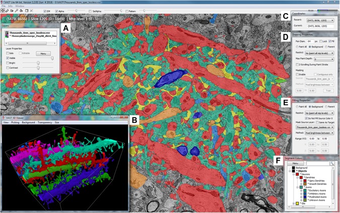
The Volume Annotation and Segmentation Tool (VAST) user interface. The main window of VAST shows an EM dataset with a manual segmentation layer as transparent overlay in which segments are colored by type (colors of collapsed folders in the “Segment Colors” tool window). The “3D Viewer” window (B) shows spiny dendrites in the area in individual colors. The tool windows A and C–F are explained further in section 2 of the main text.
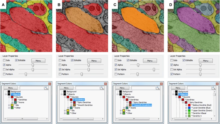
Selective segmentation display. Which segments in a segmentation layer are shown in what color depends on the selection and folder collapse state of the segment hierarchy. The top shows the appearance in the VAST main window; the middle shows the transparency and pattern settings of the segmentation layer in the “Layers” tool window, and the bottom shows the “Segmentation Colors” tool window. (A) All object type folders are closed, so all objects are shown in colors depending on their identity (Dendrite, Axon, Glia, Other). Patterns are disabled. (B) By enabling “Sel Alpha” for selective opacity control of the selected branch, disabling Alpha and selecting the “Dendrites” folder, now only dendrite segments are shown and colored depending on their subtype (spiny or smooth). (C) When “Alpha” and “Sel Alpha” are both enabled, the opacity of the selected subfolder and all other segments can be controlled separately. In this example, the segments in the “Smooth Dendrites” folder are given a higher opacity with the “Sel Alpha” slider to highlight them. (D) The folders in the segmentation hierarchy are opened such that all neurites and glial branches in the segmentation are shown with individual colors. Here patterns are enabled, showing all segments with their individual patterns. The strength of the patterning can be controlled with the “Pattern” slider.
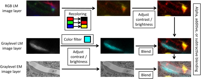
Layer blending. For each image layer, VAST can apply color filters, recolor channels of RGB images, adjust contrast and brightness, and blend the layers with different modes.
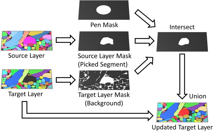
Masked painting. During painting, VAST intersects a mask of the pen tooltip (Pen Mask) with a mask derived from the target layer (Paint All, Background or Parent) and optionally, if “Masking” is enabled, a mask derived from an additional source layer (Brightness/Color range or Picked Segment) to constrain which voxels in the target layer are painted. This can for example be used to guide manual painting in the target layer by an automatic segmentation in the source layer.
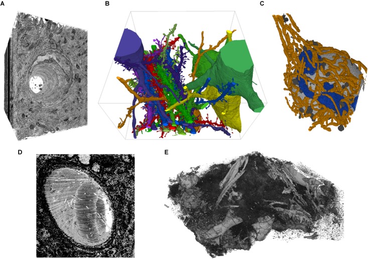
Example screenshots of the 3D viewer. (A) Capillary running through cortex, rendered from EM image stack. (B) Segmented spiny dendrites and cell bodies (fully manual segmentation). (C) Organelles in a neuron soma; mitochondria in orange, Golgi apparatus in blue, lysosomes dark gray, nucleus light gray (fully manual segmentation). (D) Erythrocyte in a capillary in LGN rendered from an EM image stack. (E) Micro-CT scan of a fossil specimen of Paleothyris acadiana (Museum of Comparative Zoology, Harvard). Data in A–C from (Kasthuri et al., 2015); D from (Morgan et al., 2016); E with kind permission of S. Pierce, Museum of Comparative Zoology, Harvard.
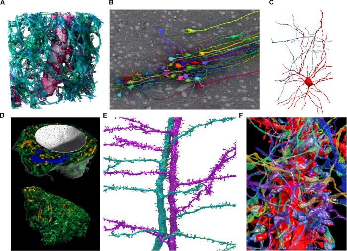
Examples of 3D models segmented in VAST and rendered in Autodesk 3ds Max. (A) Spiny dendrite (red) and axons (green) in a 10 μm × 10 μm × 6 μm cube of mouse cortex. At a voxel size of 6 nm × 6 nm × 30 nm, even the finest neural processes are segmentable. (B) Neurons traced in a low-resolution EM stack of mouse cortex, shown in situ above one EM section, with apical dendrites running in a bundle toward the pia (to the right in the image). Field of view roughly 510 × 340 micrometers. (C) Putative basket cell in rat cortex, traced semi-automatically with trans-layer masking in a ∼100 μm × 100 μm × 200 μm tissue volume. Tracing this cell took ∼15 h for a single expert. (D) Organelles in a neuron cell body (same cell as Figure 5C) shown from two directions. Nucleus white, with pores visible; endoplasmic reticulum green, mitochondria yellow, Golgi apparatus blue. (E) Two spiny apical dendrites with side branches in rat cortex. Synapses shown in yellow. (F) Spiny dendrite in red, with transparent axons making synapses on it. Neurotransmitter vesicles (white) were exported using particle clouds to generate spherical vesicles. All images are based on EM data from the lab of Jeff Lichtman, Harvard. All segmentations except C were done fully manually. A,B,D,F used data published with (Kasthuri et al., 2015).
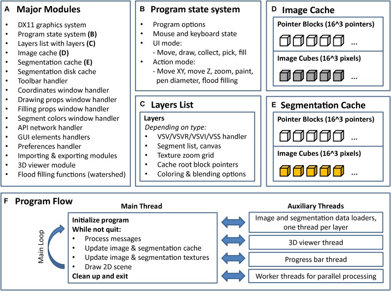
Internal program structure and control flow of VAST. VAST is structured as a collection of modules (C++ classes) which implement different parts of the program, the most important of which are listed in (A). The internal state of the program is held in a global state system class (B). Layers are kept in a linked list, with each layer holding a set of further class instances depending on type (C). There are two caching systems, one for image data (D) and one for segmentation data (E). All image layers share the image cache and all segmentation layers share the segmentation cache. (F) Shows the threading structure and the control flow of the main thread. Even though each layer has its own loader thread, cache updating is done in the main thread only to prevent multithreading problems.
References
Publication types
MeSH terms
Grants and funding
LinkOut - more resources
Full Text Sources
Other Literature Sources