

Forward dynamic optimization of handle path and muscle activity for handle based isokinetic wheelchair propulsion: A simulation study
- PMID: 30398368
- PMCID: PMC6457274
- DOI: 10.1080/10255842.2018.1527321
Forward dynamic optimization of handle path and muscle activity for handle based isokinetic wheelchair propulsion: A simulation study
Abstract
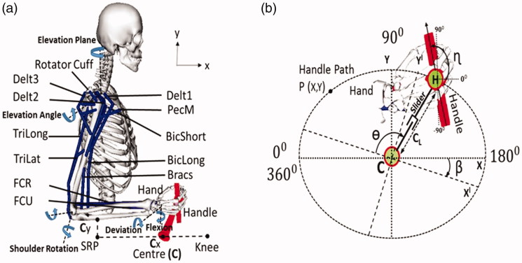
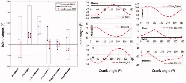
Push-rim wheelchair propulsion is biomechanically inefficient and physiologically stressful to the musculoskeletal structure of human body. This study focuses to obtain a new, optimized propulsion shape for wheelchair users, which is within the ergonomic ranges of joint motion, thus reducing the probability of injuries. To identify the propulsion movement, forward dynamic optimization was performed on a 3D human musculoskeletal model linked to a handle based propulsion mechanism, having shape and muscle excitations as optimization variables. The optimization resulted in a handle path shape with a circularity ratio of 0.95, and produced a net propulsion power of 34.7 watts for an isokinetic propulsion cycle at 50 rpm. Compared to push-rim propulsion, the compact design of the new propulsion mechanism along with the ergonomically optimized propulsion shape may help to reduce the risk of injuries and thus improve the quality of life for wheelchair users.
Keywords: Wheelchair propulsion; dynamic optimization; handle-based propulsion; musculoskeletal modelling.
Figures


Similar articles
-
A comparison of static and dynamic optimization muscle force predictions during wheelchair propulsion.J Biomech. 2014 Nov 7;47(14):3459-65. doi: 10.1016/j.jbiomech.2014.09.013. Epub 2014 Sep 23. J Biomech. 2014. PMID: 25282075 Free PMC article.
-
A preliminary muscle activity analysis: Handle based and push-rim wheelchair propulsion.J Biomech. 2019 May 24;89:119-122. doi: 10.1016/j.jbiomech.2019.04.011. Epub 2019 Apr 19. J Biomech. 2019. PMID: 31053474
-
In Vivo Biomechanical Assessment of a Novel Handle-Based Wheelchair Drive.IEEE Trans Neural Syst Rehabil Eng. 2021;29:1669-1678. doi: 10.1109/TNSRE.2021.3105388. Epub 2021 Aug 27. IEEE Trans Neural Syst Rehabil Eng. 2021. PMID: 34403347
-
Upper-limb joint kinetics expression during wheelchair propulsion.J Rehabil Res Dev. 2009;46(7):939-44. doi: 10.1682/jrrd.2008.12.0165. J Rehabil Res Dev. 2009. PMID: 20104416 Free PMC article. Review.
-
Wheelchair propulsion biomechanics and wheelers' quality of life: an exploratory review.Disabil Rehabil Assist Technol. 2011;6(5):365-77. doi: 10.3109/17483107.2010.525290. Epub 2010 Oct 11. Disabil Rehabil Assist Technol. 2011. PMID: 20932232 Review.
Cited by
-
Metabolic Cost and Mechanical Efficiency of a Novel Handle-Based Device for Wheelchair Propulsion.J Rehabil Med. 2022 Nov 23;54:jrm00346. doi: 10.2340/jrm.v54.1503. J Rehabil Med. 2022. PMID: 36264132 Free PMC article.
References
-
- Arnet U, Drongelen S, Scheel-Sailer A, Woude L, Veeger D. 2012. Shoulder load during synchronous handcycling and handrim wheelchair propulsion in persons with paraplegia. J Rehabil Med. 44(3):222–228. - PubMed
-
- Arnet U, Van Drongelen S, Veeger DJ, van der Woude LHV. 2013. Force application during handcycling and handrim wheelchair propulsion: An initial comparison. J Appl Biomech. 29(6):687–695. - PubMed
-
- Arnet U, van Drongelen S, van der Woude LHV, Veeger DHEJ. 2012. Shoulder load during handcycling at different incline and speed conditions. Clin Biomech (Bristol, Avon)). 27(1):1–6. - PubMed
-
- Boninger ML, Souza AL, Cooper RA, Fitzgerald SG, Koontz AM, Fay BT. 2002. Propulsion patterns and pushrim biomechanics in manual wheelchair propulsion. Arch Phys Med Rehabil. 83(5):718–723. - PubMed
MeSH terms
Grants and funding
LinkOut - more resources
Full Text Sources