

A Fluidic Interface with High Flow Uniformity for Reusable Large Area Resonant Biosensors
- PMID: 30400497
- PMCID: PMC6190451
- DOI: 10.3390/mi8100308
A Fluidic Interface with High Flow Uniformity for Reusable Large Area Resonant Biosensors
Abstract
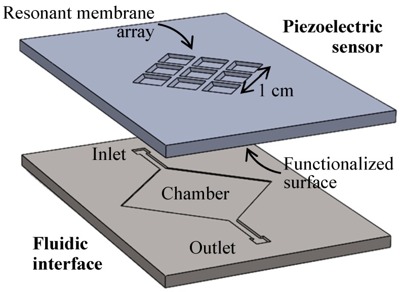
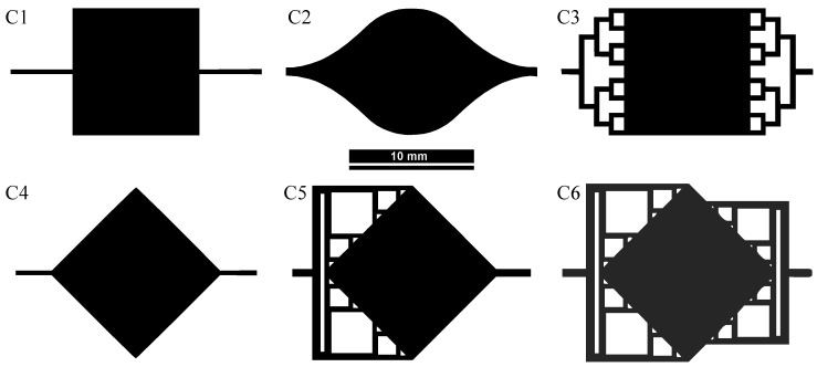
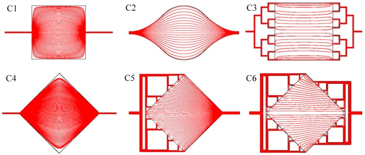
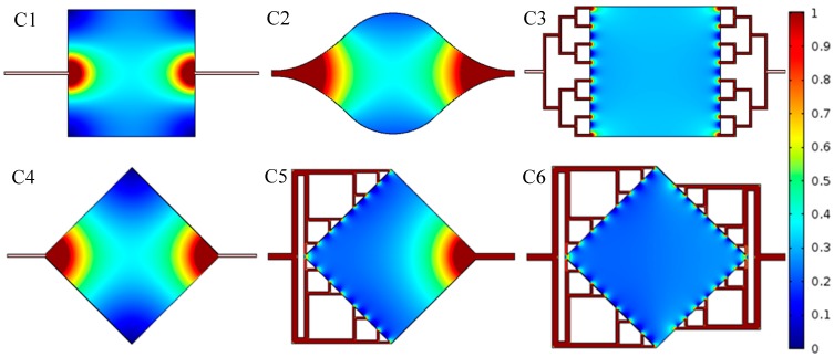
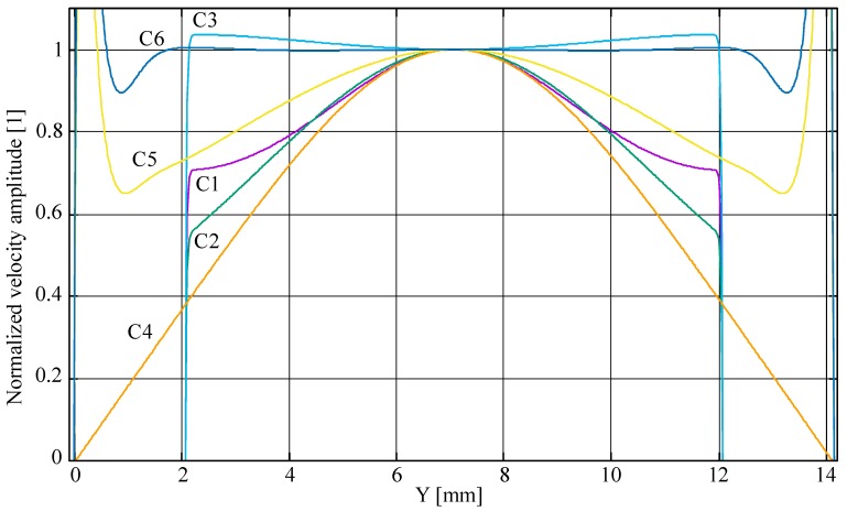
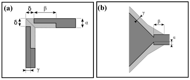
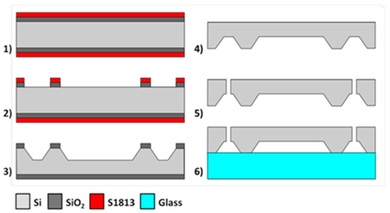
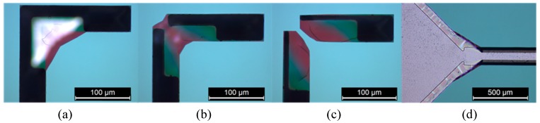
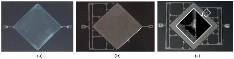
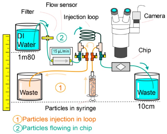
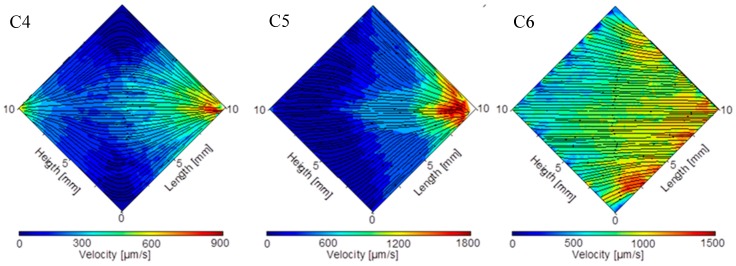
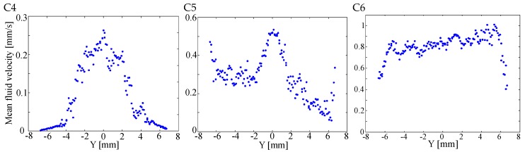
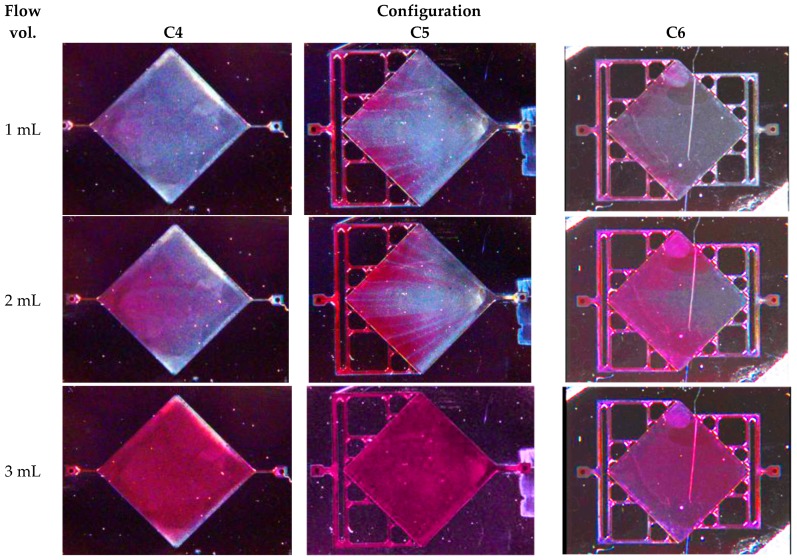
Resonant biosensors are known for their high accuracy and high level of miniaturization. However, their fabrication costs prevent them from being used as disposable sensors and their effective commercial success will depend on their ability to be reused repeatedly. Accordingly, all the parts of the sensor in contact with the fluid need to tolerate the regenerative process which uses different chemicals (H₃PO₄, H₂SO₄ based baths) without degrading the characteristics of the sensor. In this paper, we propose a fluidic interface that can meet these requirements, and control the liquid flow uniformity at the surface of the vibrating area. We study different inlet and outlet channel configurations, estimating their performance using numerical simulations based on finite element method (FEM). The interfaces were fabricated using wet chemical etching on Si, which has all the desirable characteristics for a reusable biosensor circuit. Using a glass cover, we could observe the circulation of liquid near the active surface, and by using micro-particle image velocimetry (μPIV) on large surface area we could verify experimentally the effectiveness of the different designs and compare with simulation results.
Keywords: biosensor; fluidic interface; micro-machining; microengineering; planar flow.
Conflict of interest statement
The authors declare no conflict of interest.
Figures
Similar articles
-
Analysis of Fluid Replacement in Two Fluidic Chambers for Oblique-Incidence Reflectivity Difference (OI-RD) Biosensor.Sensors (Basel). 2024 Mar 21;24(6):2000. doi: 10.3390/s24062000. Sensors (Basel). 2024. PMID: 38544262 Free PMC article.
-
Micro Fluidic Channel Machining on Fused Silica Glass Using Powder Blasting.Sensors (Basel). 2008 Feb 6;8(2):700-710. doi: 10.3390/s8020700. Sensors (Basel). 2008. PMID: 27879730 Free PMC article.
-
Biofouling Removal and Protein Detection Using a Hypersonic Resonator.ACS Sens. 2017 Aug 25;2(8):1175-1183. doi: 10.1021/acssensors.7b00298. Epub 2017 Jul 28. ACS Sens. 2017. PMID: 28730815
-
Magnetic biosensors: Modelling and simulation.Biosens Bioelectron. 2018 Apr 30;103:69-86. doi: 10.1016/j.bios.2017.12.023. Epub 2017 Dec 20. Biosens Bioelectron. 2018. PMID: 29278815 Review.
-
[Review on label-free optical bio-sensing technology based on whisper-gallery-mode].Guang Pu Xue Yu Guang Pu Fen Xi. 2010 Nov;30(11):3076-80. Guang Pu Xue Yu Guang Pu Fen Xi. 2010. PMID: 21284187 Review. Chinese.
Cited by
-
Multidisciplinary Role of Microfluidics for Biomedical and Diagnostic Applications: Biomedical Microfluidic Devices.Micromachines (Basel). 2017 Nov 27;8(12):343. doi: 10.3390/mi8120343. Micromachines (Basel). 2017. PMID: 30400533 Free PMC article.
-
Regenerable ZnO/GaAs Bulk Acoustic Wave Biosensor for Detection of Escherichia coli in "Complex" Biological Medium.Biosensors (Basel). 2021 May 7;11(5):145. doi: 10.3390/bios11050145. Biosensors (Basel). 2021. PMID: 34067116 Free PMC article.
References
-
- Wingqvist G., Yantchev V., Katardjiev I. Mass sensitivity of multiplayer thin film resonant BAW sensors. Sens. Actuators A. 2008;148:88–95. doi: 10.1016/j.sna.2008.07.023. - DOI
-
- Lin R.-E., Chen Y.-C., Chang W.-T., Cheng C.-C., Kao K.-S. Highly sensitive mass sensor using film bulk acoustic resonator. Sens. Actuators A. 2008;147:425–429. doi: 10.1016/j.sna.2008.05.011. - DOI
-
- Bao L., Qu X., Chen H., Su X., Yao S., Wei W. A bulk acoustic wave viscosity sensor for determination of lysozyme based on lysis of micrococcus lysodeikeicus. Microchim. Acta. 1999;132:61–65. doi: 10.1007/PL00010074. - DOI
Grants and funding
LinkOut - more resources
Full Text Sources
