. 2016 Jun 28;7(7):108.
doi: 10.3390/mi7070108.

3D Printed Paper-Based Microfluidic Analytical Devices

Affiliations

3D Printed Paper-Based Microfluidic Analytical Devices

Yong He et al. Micromachines (Basel). .

Abstract

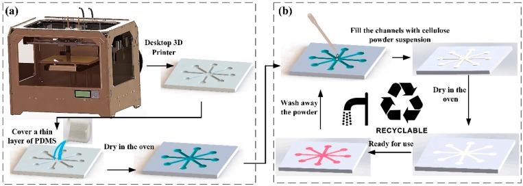
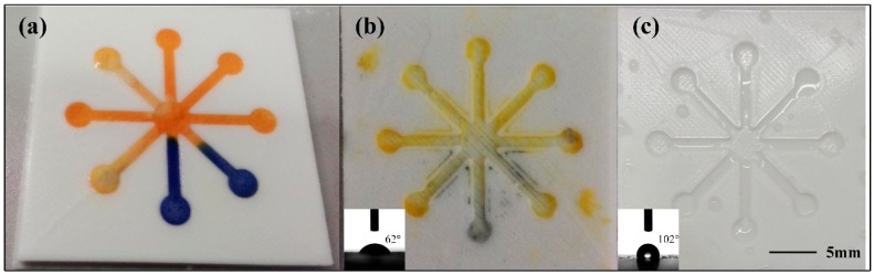
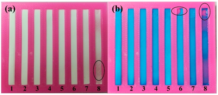
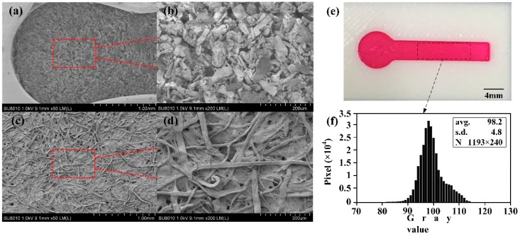
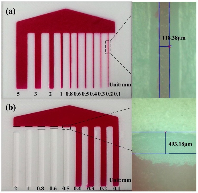
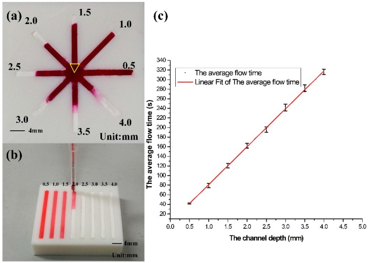
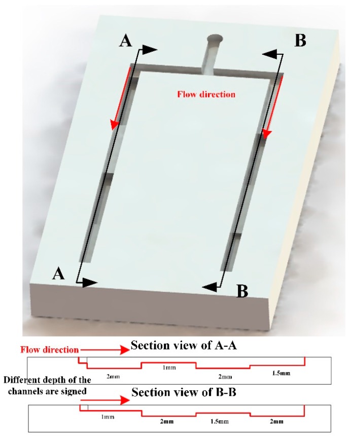
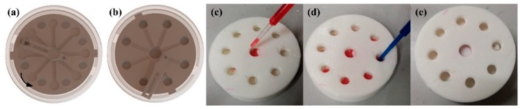
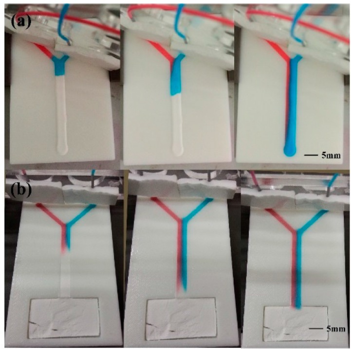
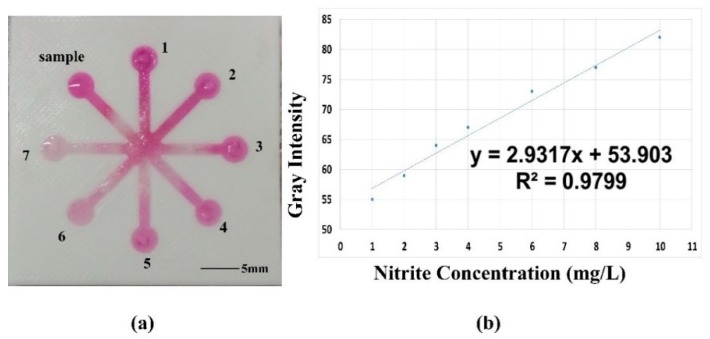
As a pump-free and lightweight analytical tool, paper-based microfluidic analytical devices (μPADs) attract more and more interest. If the flow speed of μPAD can be programmed, the analytical sequences could be designed and they will be more popular. This reports presents a novel μPAD, driven by the capillary force of cellulose powder, printed by a desktop three-dimensional (3D) printer, which has some promising features, such as easy fabrication and programmable flow speed. First, a suitable size-scale substrate with open microchannels on its surface is printed. Next, the surface of the substrate is covered with a thin layer of polydimethylsiloxane (PDMS) to seal the micro gap caused by 3D printing. Then, the microchannels are filled with a mixture of cellulose powder and deionized water in an appropriate proportion. After drying in an oven at 60 °C for 30 min, it is ready for use. As the different channel depths can be easily printed, which can be used to achieve the programmable capillary flow speed of cellulose powder in the microchannels. A series of microfluidic analytical experiments, including quantitative analysis of nitrite ion and fabrication of T-sensor were used to demonstrate its capability. As the desktop 3D printer (D3DP) is very cheap and accessible, this device can be rapidly printed at the test field with a low cost and has a promising potential in the point-of-care (POC) system or as a lightweight platform for analytical chemistry.

Keywords: 3D printing; flow speed programming; paper-based microfluidic analytical devices (μPADs).


Conflict of interest statement

The authors declared a patent about this method has been applied.

Figures

Figure 1
Figure 1
Fabrication process of microfluidic analytical device: (a) Substrate fabrication process; (b) Recyclable fabrication process of the hydrophilic cellulose powder channels.
Figure 2
Figure 2
Comparison between the PDMS coated substrate and uncoated substrate: (a) PH test on the fabricated microfluidic device; (b) PDMS uncoated substrate washed by water after PH test (inset: water contact angle image of PDMS uncoated substrate); (c) PDMS coated substrate washed by water after PH test (inset: water contact angle image of PDMS coated substrate).
Figure 3
Figure 3
Cellulose powder channels fabricated with different proportion: (a) Comparison between the fabricated channels; (b) Blue dye was dropped to test the channels’ quality.
Figure 4
Figure 4
Scanning electron microscopy of cellulose powder in fabricated device and Whatman No. 1: (a) Microstructure of cellulose powder under microscope (50×); (b) Microstructure of cellulose powder under microscope (200×); (c) Microstructure of chromatography paper Whatman No. 1 under microscope (50×); (d) Microstructure of chromatography paper Whatman No. 1 under microscope (200×); (e) A dying test on a μ3DPAD with a channel of 4 mm width; (f) Gray value distribution of the dye in the channel.
Figure 5
Figure 5
Resolution of μ3DPADs: (a) The resolution of the hydrophilic channels and the channel’s image under the microscope (100×); (b) The resolution of the hydrophobic barriers and the barrier's image under the microscope (100×).
Figure 6
Figure 6
Relationship between channel depth and flow time: (a) The flow trend of red dye in 8 channels with a gradient depth; (b) Quantitative analysis on the relationship between channel depth and flow time; (c) The linear relationship of speed and the depth.
Figure 7
Figure 7
Flow speed control in 3D channels. The left channel and the right channel all have four segments with the different depth and the same segment length.
Figure 8
Figure 8
The encapsulation of the microfluidic analytical device: (a) Model graph of the device in closed state; (b) Model graph of the device in open state; (c) Dropping indicating solution in physical model in open state; (d) Dropping test solution in physical model in open state; (e) Physical model graph of the device in closed state.
Figure 9
Figure 9
Time-lapse image of two different dyes diffusing in the fabricated Y device: (a) Microfluidic Y device with two different fluid path lengths; (b) Microfluidic Y device with the same path length.
Figure 10
Figure 10
Colorimetric assay of nitrite via color-reaction by using microfluidic analytical device: (a) Image of the testing microfluidic analytical device; (b) Curve for nitrite ion.

References

    1. He Y., Wu Y., Fu J.Z., Wu W.B. Fabrication of paper-based microfluidic analysis devices: A review. RSC Adv. 2015;5:78109–78127. doi: 10.1039/C5RA09188H. - DOI
    1. Martinez A.W., Phillips S.T., Butte M.J., Whitesides G.M. Patterned paper as a platform for inexpensive, low-volume, portable bioassays. Angew. Chem. Int. Ed. 2007;46:1318–1320. doi: 10.1002/anie.200603817. - DOI - PMC - PubMed
    1. Cate D.M., Adkins J.A., Mettakoonpitak J., Henry C.S. Recent Developments in Paper-Based Microfluidic Devices. Anal. Chem. 2014;87:19–41. doi: 10.1021/ac503968p. - DOI - PubMed
    1. Tang M., Wang G., Kong S.K., Ho H.P. A Review of Biomedical Centrifugal Microfluidic Platforms. Micromachines. 2016;7:26. doi: 10.3390/mi7020026. - DOI - PMC - PubMed
    1. Lu Y., Shi W., Jiang L., Qin J., Lin B. Rapid prototyping of paper-based microfluidics with wax for low-cost, portable bioassay. Electrophoresis. 2009;30:1497–1500. doi: 10.1002/elps.200800563. - DOI - PubMed