. 2016 Jul 14;7(7):120.
doi: 10.3390/mi7070120.

Cytostretch, an Organ-on-Chip Platform

Affiliations

Cytostretch, an Organ-on-Chip Platform

Nikolas Gaio et al. Micromachines (Basel). .

Abstract

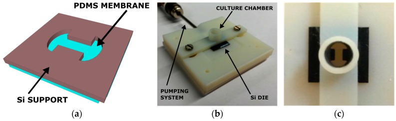
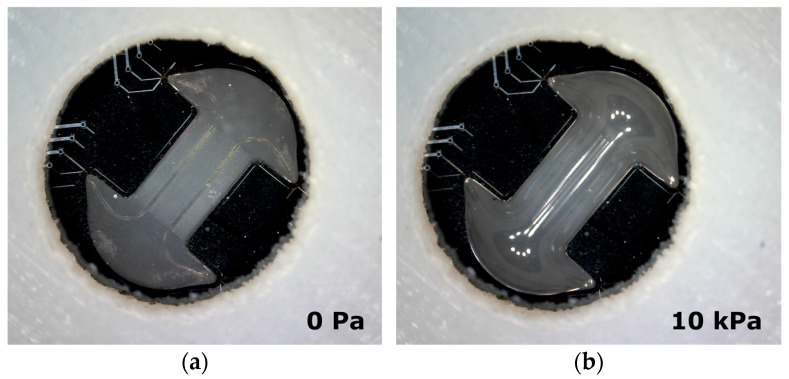
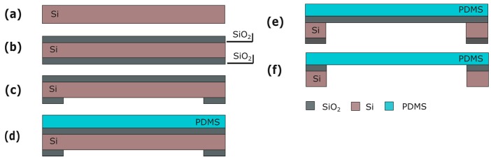
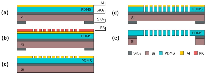
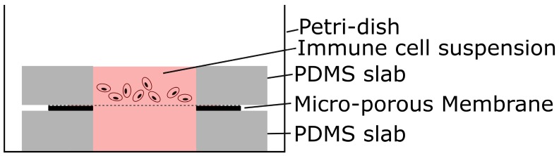
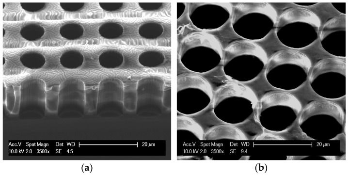
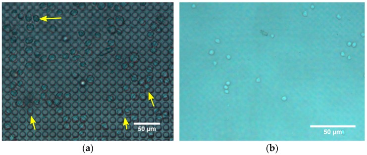
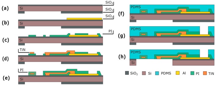
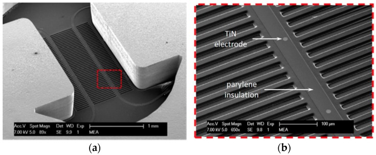
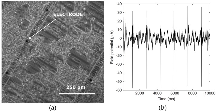
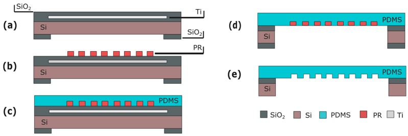
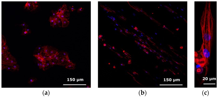
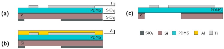
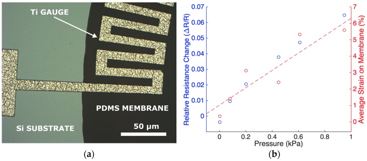
Organ-on-Chips (OOCs) are micro-fabricated devices which are used to culture cells in order to mimic functional units of human organs. The devices are designed to simulate the physiological environment of tissues in vivo. Cells in some types of OOCs can be stimulated in situ by electrical and/or mechanical actuators. These actuations can mimic physiological conditions in real tissue and may include fluid or air flow, or cyclic stretch and strain as they occur in the lung and heart. These conditions similarly affect cultured cells and may influence their ability to respond appropriately to physiological or pathological stimuli. To date, most focus has been on devices specifically designed to culture just one functional unit of a specific organ: lung alveoli, kidney nephrons or blood vessels, for example. In contrast, the modular Cytostretch membrane platform described here allows OOCs to be customized to different OOC applications. The platform utilizes silicon-based micro-fabrication techniques that allow low-cost, high-volume manufacturing. We describe the platform concept and its modules developed to date. Membrane variants include membranes with (i) through-membrane pores that allow biological signaling molecules to pass between two different tissue compartments; (ii) a stretchable micro-electrode array for electrical monitoring and stimulation; (iii) micro-patterning to promote cell alignment; and (iv) strain gauges to measure changes in substrate stress. This paper presents the fabrication and the proof of functionality for each module of the Cytostretch membrane. The assessment of each additional module demonstrate that a wide range of OOCs can be achieved.

Keywords: Cytostretch; customizable; micro-electrode array; micro-grooves; modular; organ-on-chip; platform; stem cells; strain gauges; through-membrane pores.


Conflict of interest statement

The authors declare no conflict of interest.

Figures

Figure 1
Figure 1
(a) Back view of the 3D sketch of the Cytostretch; (b) Example of a 3D-printed holder for the Cytostretch, including a cell culture chamber on top of the die and a pumping system to inflate the membrane; (c) Top view of the device mounted in the holder.
Figure 2
Figure 2
(a) Cytostretch (with MEA module embedded) at relaxed state; (b) The Cytostretch device during inflation by applying an air pressure of 10 kPa on the back of the membrane.
Figure 3
Figure 3
Process flow for the product platform: (a) Si wafer; (b) PECVD SiO2 deposition; (c) Back SiO2 patterning; (d) PDMS deposition; (e) DRIE Si etching; (f) Wet SiO2 etching. Figures are not to scale.
Figure 4
Figure 4
Process flow for the through-membrane micro-pore array: (a) Al sputtering; (b) PR spinning and patterning; (c) Al patterning; (d) PDMS patterning; (e) Membrane releasing. Figures are not to scale.
Figure 5
Figure 5
Schematic of setup for simple migration experiment.
Figure 6
Figure 6
SEM images of microporous PDMS membranes: (a) 15-µm-thick membrane with through-membrane pores 8 µm in diameter; (b) 9-µm-thick membrane with through-membrane pores 14 µm in diameter.
Figure 7
Figure 7
Phase contrast images of migration experiment. (a) The top of the micro-porous membrane 5 min after seeding shows immune cells resting on pores; (b) The volume below the membrane 3.5 h after seeding shows immune cells floating.
Figure 8
Figure 8
Process flow for the MEA module: (a) Substrate; (b) Al deposition and patterning; (c) First layer of polyimide (or, alternatively, parylene) is spun and patterned; (d) TiN deposition and patterning; (e) Second layer of polyimide (or, alternatively, parylene) is spun and patterned; (f) PDMS deposition; (g) PDMS patterning; (h) Membrane releasing. Figures are not to scale.
Figure 9
Figure 9
(a) SEM image of the Cytostretch chip from the back; (b) Close-up of the area highlighted in (a) depicting transversal micro-grooves, the exposed TiN electrodes and parylene insulation of the metal tracks. Adapted from [25].
Figure 10
Figure 10
(a) Optical images of cardiac induced pluripotent stem cell (iPSC) on the Cytostretch device; (b) The field potential recording from one of the electrodes.
Figure 11
Figure 11
Process flow for the micro-groove module: (a) Substrate with Ti mask embedded in the front-side SiO2 layer; (b) PR spinning and patterning; (c) PDMS patterning; (d) Membrane releasing; (e) PR stripping. Figures are not to scale.
Figure 12
Figure 12
Confocal images of hPSC-CMs stained for anti-alpha-actinin (red) and DAPI (blue) to reveal the sarcomeric structure and cell nucleus. (a) hPSC-CM on plain PDMS; (b,c) hPSC-CM on micro-patterned PDMS.
Figure 13
Figure 13
Process flow for the strain gauges: (a) Ti deposition and patterning; (b) Al deposition; (c) membrane releasing and Al etching. The figures are not to scale.
Figure 14
Figure 14
Measurement setup (a) and custom-made holder (b) used to measure the resistance change of the Ti strain gauges in the Cytostretch membrane platform.
Figure 15
Figure 15
(a) Optical image from the front side showing a close-up of the Ti gauges at the interface between the silicon substrate and the PDMS membrane. As presented in [33], the strain gauges were fabricated on circular membranes; (b) Relative resistance change of a strain gauge (primary Y axis) and the average strain on the membrane (secondary Y-axis) as function of pressure.

References

    1. Gassmann O., Reepmeyer G., von Zedtwitz M. Leading Pharmaceutical Innovation. Springer Science & Business Media; Berlin, Germany: 2008. Trends and drivers for growth in the pharmaceutical industry.
    1. Beißner N., Lorenz T., Reichl S. Microsystems for Pharmatechnology. Springer International Publishing; Gewerbestrasse, Switzerland: 2016. Organ on chip; pp. 299–339.
    1. Van der Meer A.D., van den Berg A. Organs-on-chips: Breaking the in vitro impasse. Integr. Biol. 2012;4:461–470. doi: 10.1039/c2ib00176d. - DOI - PubMed
    1. Van de Stolpe A., den Toonder J. Workshop meeting report Organs-on-Chips: Human disease models. Lab Chip. 2013;13:3449–3470. doi: 10.1039/c3lc50248a. - DOI - PubMed
    1. Jo B.H., van Lerberghe L.M., Motsegood K.M., Beebe D.J. Three-dimensional micro-channel fabrication in polydimethylsiloxane (PDMS) elastomer. J. Microelectromech. Syst. 2000;9:76–81. doi: 10.1109/84.825780. - DOI

LinkOut - more resources