Analytical solution for converging elliptic shear wave in a bounded transverse isotropic viscoelastic material with nonhomogeneous outer boundary
- PMID: 30404507
- PMCID: PMC6197985
- DOI: 10.1121/1.5064372
Analytical solution for converging elliptic shear wave in a bounded transverse isotropic viscoelastic material with nonhomogeneous outer boundary
Abstract
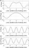
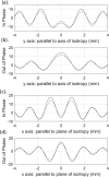
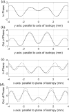
Dynamic elastography methods-based on optical, ultrasonic, or magnetic resonance imaging-are being developed for quantitatively mapping the shear viscoelastic properties of biological tissues, which are often altered by disease and injury. These diagnostic imaging methods involve analysis of shear wave motion in order to estimate or reconstruct the tissue's shear viscoelastic properties. Most reconstruction methods to date have assumed isotropic tissue properties. However, application to tissues like skeletal muscle and brain white matter with aligned fibrous structure resulting in local transverse isotropic mechanical properties would benefit from analysis that takes into consideration anisotropy. A theoretical approach is developed for the elliptic shear wave pattern observed in transverse isotropic materials subjected to axisymmetric excitation creating radially converging shear waves normal to the fiber axis. This approach, utilizing Mathieu functions, is enabled via a transformation to an elliptic coordinate system with isotropic properties and a ratio of minor and major axes matching the ratio of shear wavelengths perpendicular and parallel to the plane of isotropy in the transverse isotropic material. The approach is validated via numerical finite element analysis case studies. This strategy of coordinate transformation to equivalent isotropic systems could aid in analysis of other anisotropic tissue structures.
Figures


Similar articles
-
Analytical solution for diverging elliptic shear wave in bounded and unbounded transverse isotropic viscoelastic material with nonhomogeneous inner boundary.J Acoust Soc Am. 2019 Jan;145(1):EL59. doi: 10.1121/1.5088028. J Acoust Soc Am. 2019. PMID: 30710967 Free PMC article.
-
Converging super-elliptic torsional shear waves in a bounded transverse isotropic viscoelastic material with nonhomogeneous outer boundary.J Acoust Soc Am. 2019 Nov;146(5):EL451. doi: 10.1121/1.5134657. J Acoust Soc Am. 2019. PMID: 31795656 Free PMC article.
-
Measurement of anisotropic mechanical properties in porcine brain white matter ex vivo using magnetic resonance elastography.J Mech Behav Biomed Mater. 2018 Mar;79:30-37. doi: 10.1016/j.jmbbm.2017.11.045. Epub 2017 Dec 9. J Mech Behav Biomed Mater. 2018. PMID: 29253729 Free PMC article.
-
Modelling the impulse diffraction field of shear waves in transverse isotropic viscoelastic medium.Phys Med Biol. 2015 May 7;60(9):3639-54. doi: 10.1088/0031-9155/60/9/3639. Epub 2015 Apr 16. Phys Med Biol. 2015. PMID: 25880794
-
The combined importance of finite dimensions, anisotropy, and pre-stress in acoustoelastography.J Acoust Soc Am. 2022 Apr;151(4):2403. doi: 10.1121/10.0010110. J Acoust Soc Am. 2022. PMID: 35461517 Free PMC article. Review.
Cited by
-
Quantifying uniaxial prestress and waveguide effects on dynamic elastography estimates for a cylindrical rod.J Acoust Soc Am. 2023 Dec 1;154(6):3580-3594. doi: 10.1121/10.0022581. J Acoust Soc Am. 2023. PMID: 38038614 Free PMC article.
-
Numerical simulation of wave propagation through interfaces using the extended finite element method for magnetic resonance elastography.J Acoust Soc Am. 2022 May;151(5):3481. doi: 10.1121/10.0011392. J Acoust Soc Am. 2022. PMID: 35649898 Free PMC article.
-
Micro Air-Pulse Spatial Deformation Spreading Characterizes Degree of Anisotropy in Tissues.IEEE J Sel Top Quantum Electron. 2021 Jul-Aug;27(4):6800810. doi: 10.1109/jstqe.2020.3038633. Epub 2020 Nov 17. IEEE J Sel Top Quantum Electron. 2021. PMID: 33994766 Free PMC article.
-
Analytical solution based on spatial distortion for a time-harmonic Green's function in a transverse isotropic viscoelastic solid.J Acoust Soc Am. 2021 Apr;149(4):2283. doi: 10.1121/10.0004133. J Acoust Soc Am. 2021. PMID: 33940868 Free PMC article.
-
Analytical solution for diverging elliptic shear wave in bounded and unbounded transverse isotropic viscoelastic material with nonhomogeneous inner boundary.J Acoust Soc Am. 2019 Jan;145(1):EL59. doi: 10.1121/1.5088028. J Acoust Soc Am. 2019. PMID: 30710967 Free PMC article.
References
Publication types
MeSH terms
Grants and funding
LinkOut - more resources
Full Text Sources

