. 2018 Nov 7;9(1):4661.
doi: 10.1038/s41467-018-07052-w.

Biological plausibility and stochasticity in scalable VO2 active memristor neurons

Affiliations

Biological plausibility and stochasticity in scalable VO2 active memristor neurons

Wei Yi et al. Nat Commun. .

Abstract

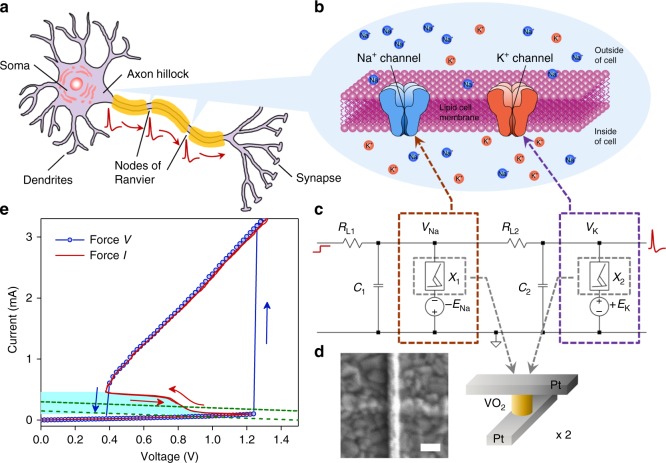
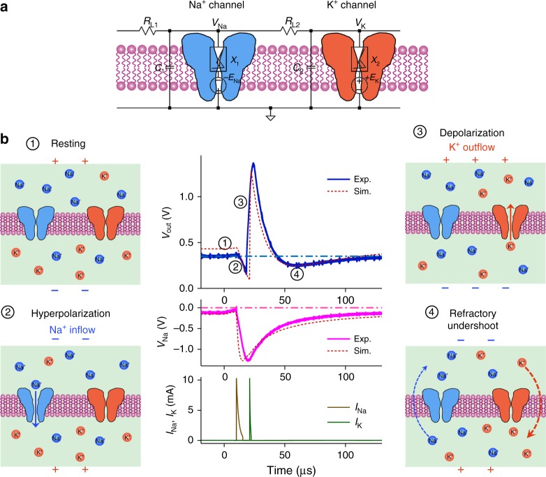
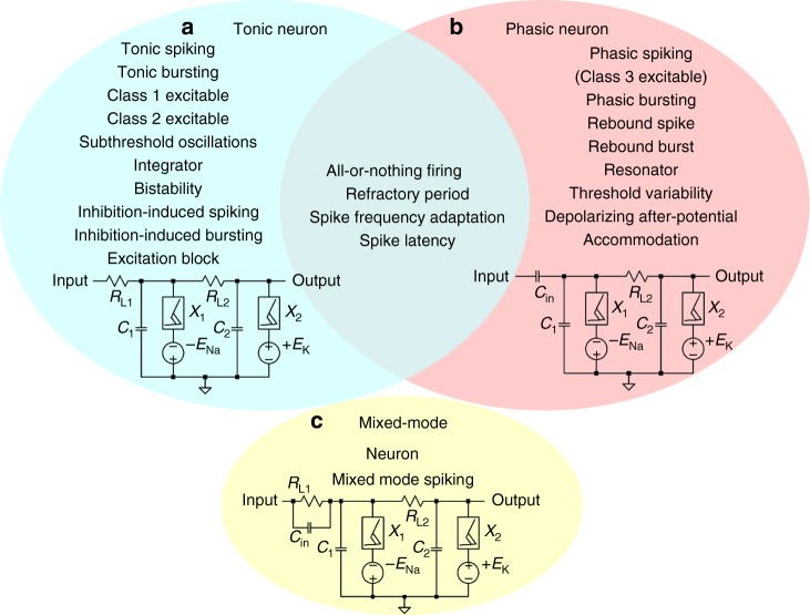
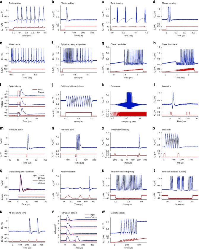
Neuromorphic networks of artificial neurons and synapses can solve computationally hard problems with energy efficiencies unattainable for von Neumann architectures. For image processing, silicon neuromorphic processors outperform graphic processing units in energy efficiency by a large margin, but deliver much lower chip-scale throughput. The performance-efficiency dilemma for silicon processors may not be overcome by Moore's law scaling of silicon transistors. Scalable and biomimetic active memristor neurons and passive memristor synapses form a self-sufficient basis for a transistorless neural network. However, previous demonstrations of memristor neurons only showed simple integrate-and-fire behaviors and did not reveal the rich dynamics and computational complexity of biological neurons. Here we report that neurons built with nanoscale vanadium dioxide active memristors possess all three classes of excitability and most of the known biological neuronal dynamics, and are intrinsically stochastic. With the favorable size and power scaling, there is a path toward an all-memristor neuromorphic cortical computer.


Conflict of interest statement

The authors declare no competing interests.

Figures

Fig. 1
Fig. 1
Circuit diagram of a biomimetic active memristor neuron and active memristor device characteristics. a Schematic structure of a biological neuron, showing that an action potential is fired near the axon hillock (under sufficient input stimulus) and propagates along the cell axon towards the output synapses. b Mechanism of voltage-gated Na+ and K+ ion flows across the cell membrane that accounts for the action potential generation and repetition across the nodes of Ranvier (myelin-sheath gaps). A similar mechanism exists in neurons that lack a myelin sheath. c Basic circuit topology of a two-channel active memristor neuron to emulate the neuronal dynamics in (b). A voltage-gated Na+ (K+) channel is emulated by a negatively (positively) d.c. biased active memristor device, which is closely coupled with a local membrane capacitor C1 (C2) and a series load resistor RL1 (RL2). d Schematic structure and a scanning electron micrograph of a typical VO2 active memristor nano-crossbar device (X1 or X2 in (c)). Scale bar: 100 nm. e Typical two-terminal quasi d.c. voltage-controlled (force V) and current-controlled (force I) IV characteristics of a VO2 active memristor device. A wide hysteresis loop exists in the voltage-controlled mode due to the Mott transitions (blue arrows). The same Mott transitions are manifested by an “S” shaped negative differential resistance (NDR) regime (highlighted by cyan color) with a much narrower hysteresis (red arrows) in the current-controlled mode. In its resting state, the resistor load line for memristor X1 (or X2) intersects with its IV loci outside the NDR regime (green dotted line). An input current or voltage stimulus can shift the load line into the NDR regime (green dashed line) and elicit an action potential generation (spiking)
Fig. 2
Fig. 2
Action potential generation in a VO2 active memristor neuron. a Circuit diagram of a VO2 memristor neuron, consisting of two resistively coupled Pearson-Anson relaxation oscillators (RL1, C1, X1 and RL2, C2, X2, respectively). The negatively-biased memristor X1 acts as the voltage-gated Na+ channel, and the positively-biased memristor X2 acts as the voltage-gated K+ channel. Capacitors C1 and C2 are the corresponding membrane capacitances. b Basic steps in action potential (spike) generation of a VO2 neuron. (1) Resting state, in which both the Na+ and K+ channels are closed. A resting potential of 0.2–0.3 V is produced by a membrane leakage current flowing through the VO2 devices in their insulating state. (2) Hyperpolarization caused by the activation of the Na+ channel, which drives the membrane potential toward negative direction. (3) Depolarization caused by the activation of the K+ channel, which drives the membrane potential toward positive direction. (4) Refractory (undershoot), during which the neuron is recovering and does not respond to another stimulus. The central plots are experimental and simulated action potentials (top), the Na+ channel membrane potential VNa (middle), and simulated Na+ and K+ channel currents (bottom)
Fig. 3
Fig. 3
Three active memristor prototype neuron circuits and their experimentally demonstrated spiking behaviors. a Tonic excitatory neurons, with a resistive coupling to dendritic inputs, show tonic spiking (Supplementary Fig. 13), tonic bursting (Supplementary Fig. 14), Class 1 excitable (Fig. 4g), Class 2 excitable (Fig. 4h), subthreshold oscillations (Supplementary Fig. 18), integrator (Supplementary Fig. 19), bistability (Supplementary Fig. 20), inhibition-induced spiking (Supplementary Fig. 21), inhibition-induced bursting (Supplementary Fig. 22), and excitation block (Supplementary Fig. 23). b Phasic excitatory neurons, with a capacitive coupling to dendritic inputs, show phasic spiking, i.e., Class 3 excitable (Supplementary Fig. 25), phasic bursting (Supplementary Fig. 26), rebound spike (Supplementary Figs. 27–29), rebound burst (Supplementary Fig. 30), resonator (Supplementary Fig. 24), threshold variability (Supplementary Fig. 31), depolarizing after-potential (Supplementary Fig. 32), and accommodation (Supplementary Fig. 33). Other biological neuron spiking behaviors, including all-or-nothing firing (Supplementary Fig. 10), refractory period (Supplementary Figs. 11 and 12), spike frequency adaptation (Supplementary Figs. 15 and 16), and spike latency (Supplementary Fig. 17), are shared properties of both tonic and phasic neurons. c mixed-mode neurons, with both resistive and capacitive couplings (RL1, Cin in parallel) to dendritic inputs, show mixed-mode spiking (Supplementary Fig. 34) behavior
Fig. 4
Fig. 4
The 23 biological neuron spiking behaviors experimentally demonstrated in single VO2 active memristor neurons. a Tonic spiking. b Phasic spiking. c Tonic bursting. d Phasic bursting. e Mixed mode. f Spike frequency adaptation. g Class 1 excitable. h Class 2 excitable. i Spike latency. j Subthreshold oscillations. k Resonator. l Integrator. m Rebound spike. n Rebound burst. o Threshold variability. p Bistability. q Depolarizing after-potential. r Accommodation. s Inhibition-induced spiking. t Inhibition-induced bursting. u All-or-nothing firing. v Refractory period. w Excitation block. All the behaviors are measured from a single tonic, phasic, or mixed-mode neuron circuit that consist of only 2 VO2 active memristors and 4 or 5 passive R, C elements. For more details, see Supplementary Figs. 10–34
Fig. 5
Fig. 5
Capacitance-dependent operating regimes in a tonic VO2 active memristor neuron. a Diagram of operating regimes determined by the values of C1 and C2 membrane capacitors. When C2 > C1, the neuron exhibits Class 2 excitable spiking and subthreshold oscillations (see (b)). When C2 < C1, the neuron exhibits Class 1 excitable spiking (see (c)). When C2 < 0.35C1, the neuron exhibits Class 1 excitable bursting (see (d)). Various combinations of C1 and C2 are sampled (colored dots) by measuring time dependence of neuron output with a linearly ramped input current. (bd) Typical neuron input and output vs. time (top panels), and the current-dependence of instantaneous spike frequency (bottom panels) sampled from Class 2 excitable spiking, Class 1 excitable spiking, and Class 1 excitable bursting regimes, respectively
Fig. 6
Fig. 6
Stochastically phase-locked firing (skipping) in a tonic VO2 active memristor neuron. ad Tonic spike trains excited by an input d.c. current of 82.5 µA amplitude and 35 ms duration. For clarity, only the initial sections of ~3 ms duration are displayed. White noise signals with 5 µApp, 15 µApp, 25 µApp, and 50 µApp peak-to-peak values, respectively, are added to the current input to study its impact on the firing pattern and the correlation between consecutive interspike intervals (ISIs). eh Joint interspike interval (JISI) scatter plots (aka return maps) of the spike trains shown in (ad). Also shown are the histograms of the ISI distributions. The numbers of spikes used to generate the JISI plots are 1149, 1113, 620, and 754, respectively

References

    1. Xia Q, et al. Memristor-CMOS hybrid integrated circuits for reconfigurable logic. Nano. Lett. 2009;9:3640–3645. doi: 10.1021/nl901874j. - DOI - PubMed
    1. Khiat A, Ayliffe P, Prodromakis T. High density crossbar arrays with sub- 15 nm single cells via liftoff process only. Sci. Rep. 2016;6:32614. doi: 10.1038/srep32614. - DOI - PMC - PubMed
    1. Kim S, et al. Experimental demonstration of a second-order memristor and its ability to biorealistically implement synaptic plasticity. Nano. Lett. 2015;15:2203–2211. doi: 10.1021/acs.nanolett.5b00697. - DOI - PubMed
    1. Wang Z, et al. Memristors with diffusive dynamics as synaptic emulators for neuromorphic computing. Nat. Mater. 2016;16:101–108. doi: 10.1038/nmat4756. - DOI - PubMed
    1. Pickett MD, Medeiros-Ribeiro G, Williams RS. A scalable neuristor built with Mott memristors. Nat. Mater. 2013;12:114–117. doi: 10.1038/nmat3510. - DOI - PubMed

Publication types