Review
. 2016 Apr 15;7(4):70.
doi: 10.3390/mi7040070.

Optofluidic Device Based Microflow Cytometers for Particle/Cell Detection: A Review

Affiliations
Review

Optofluidic Device Based Microflow Cytometers for Particle/Cell Detection: A Review

Yushan Zhang et al. Micromachines (Basel). .

Abstract

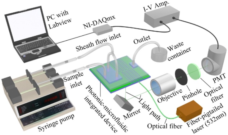
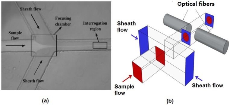
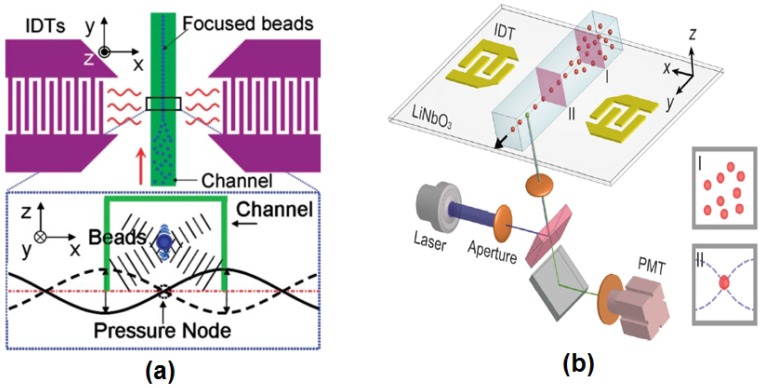
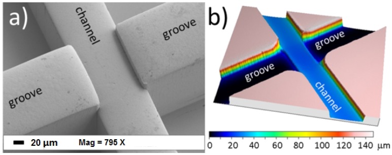
Optofluidic devices combining micro-optical and microfluidic components bring a host of new advantages to conventional microfluidic devices. Aspects, such as optical beam shaping, can be integrated on-chip and provide high-sensitivity and built-in optical alignment. Optofluidic microflow cytometers have been demonstrated in applications, such as point-of-care diagnostics, cellular immunophenotyping, rare cell analysis, genomics and analytical chemistry. Flow control, light guiding and collecting, data collection and data analysis are the four main techniques attributed to the performance of the optofluidic microflow cytometer. Each of the four areas is discussed in detail to show the basic principles and recent developments. 3D microfabrication techniques are discussed in their use to make these novel microfluidic devices, and the integration of the whole system takes advantage of the miniaturization of each sub-system. The combination of these different techniques is a spur to the development of microflow cytometers, and results show the performance of many types of microflow cytometers developed recently.

Keywords: microfabrication; microflow cytometer; microfluidics; optofluidic device.


Conflict of interest statement

The authors declare no conflict of interest.

Figures

Figure 1
Figure 1
System setup of an optofluidic device (also referred to as photonic-microfluidic integrated device)-based microflow cytometer. Laser light is focused through on-chip lenses, and side scattered light (SSC) and fluorescence light (FL) signals are detected via free-space lens system. Light signals are amplified by a photomultiplier tube (PMT), then data are analyzed by a data acquisition card (DAQ). Reproduced from [20] with kind permission from Wiley.
Figure 2
Figure 2
Reported hydrodynamic focusing methods in a microflow cytometer. (a) A typical structure of 2D hydrodynamic focusing. Reproduced from [24]. (b) A straight forward 3D hydrodynamic focusing structure. Reprinted from [31] with kind permission from OSA Publishing.
Figure 3
Figure 3
(a) A schematic diagram of standing surface acoustic waves (SSAW) focusing. The pressure node located at the center of the microchannel was generated by the SSAW field created by two parallel interdigital transducers (IDTs). When particles or cells enter the SSAW field, the acoustic radiation force (vertically and horizontally) moves the particles to the pressure node. Reprinted from [39] with kind permission from Royal Society of Chemistry. (b) A schematic diagram of a SSAW-based microflow cytometer. Reprinted from [41] with kind permission from Royal Society of Chemistry.
Figure 4
Figure 4
(a) SEM microgram of microgrooves for optical fibers. (b) confocal microscope profilometry of the microchip that shows the depths of microchannel and microgrooves. Reproduced from [56] from Micromachines published by MDPI.
Figure 5
Figure 5
(a) SEM images of four microflow cytometers with different optical systems. Long straight waveguides direct lights to the lens system; waveguides at different angles are used to collect signals. (b) Images of angled input waveguides and the lens system to reduce background noise for SSC and FSC detection. (c) SEM images of on-chip air lens system without notches. (d) SEM images of on-chip air lens system with notches. Reproduced from Watts [65] with permission.
Figure 6
Figure 6
Beam shaping simulation results and fluorescent images of formed beam shape. (a) ZEMAX simulation results of 3.6-µm and 10-µm on-chip beam shaping lens systems. (b) Fluorescent image of the input excitation beam input directly from a waveguide without any lens. (c) Fluorescent image of formed beam shape after passing through a 10-µm beam shaping lens system. Reprinted from [67] with permission from OSA Publishing.
Figure 7
Figure 7
ZEMAX simulations for a 3-µm lens system that inserts a notch for forward scattered light detection. Note how the notch is re-imaged on the waveguide behind the channel. Reprinted from [65] with permission.
Figure 8
Figure 8
(a) SEM image of a waveguide facet. (b) A close-up SEM image of a waveguide facet showing the smooth optical coupling face. Reprinted from [65] with permission.
Figure 9
Figure 9
Data analysis results of a mixture of beads and cells flowing in an optofluidic microflow cytometer. (a) One second raw data of SSC signal intensity from a test with a mixture of E. coli cells and beads of 2 µm and 4 µm in diameter. (b1) Statistical histograms of events by total beads and E. coli cells with intensity on a logarithmic scale. (b2) Statistical histograms of events produced by E. coli cells on a linear scale and its Gaussian fitting. (b3) Statistical histograms of events by beads with intensity on a linear scale and Gaussian fittings. Reprinted from [20] with permission from Wiley.
Figure 10
Figure 10
A schematic diagram showing the integration of a multilayered PDMS/SU-8 device. SU-8 is the functional layer; PDMS covers and seals the device; and glass pads allow solid fluidic interconnects. Reproduced from [65] with permission.
Figure 11
Figure 11
Standard fabrication procedure of a PDMS/SU-8 device. Reprinted from [81] from Micromachines published by MDPI.

Similar articles

Cited by

References

    1. Piyasena M.E., Graves S.W. The intersection of flow cytometry with microfluidics and microfabrication. Lab Chip. 2014;14:1044–1059. doi: 10.1039/c3lc51152a. - DOI - PMC - PubMed
    1. Barat D., Spencer D., Benazzi G., Mowlem M.C., Morgan H. Simultaneous high speed optical and impedance analysis of single particles with a microfluidic cytometer. Lab Chip. 2012;12:118–126. doi: 10.1039/C1LC20785G. - DOI - PubMed
    1. Volpatti L.R., Yetisen A.K. Commercialization of microfluidic devices. Trends Biotechnol. 2014;32:347–350. doi: 10.1016/j.tibtech.2014.04.010. - DOI - PubMed
    1. Psaltis D., Quake S.R., Yang C. Developing optofluidic technology through the fusion of microfluidics and optics. Nature. 2006;442:381–386. doi: 10.1038/nature05060. - DOI - PubMed
    1. Horowitz V.R., Awschalow D.D., Pennathur S. Optofluidics: Field or technique? Lab Chip. 2008;8:1856–1863. - PubMed

LinkOut - more resources