. 2018 Dec;12(6):1230-1245.
doi: 10.1109/TBCAS.2018.2880148. Epub 2018 Nov 7.

A Chronically Implantable Neural Coprocessor for Investigating the Treatment of Neurological Disorders

A Chronically Implantable Neural Coprocessor for Investigating the Treatment of Neurological Disorders

Scott Stanslaski et al. IEEE Trans Biomed Circuits Syst. 2018 Dec.

Abstract

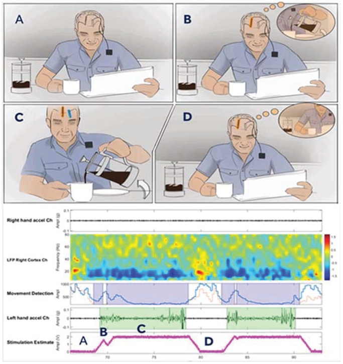
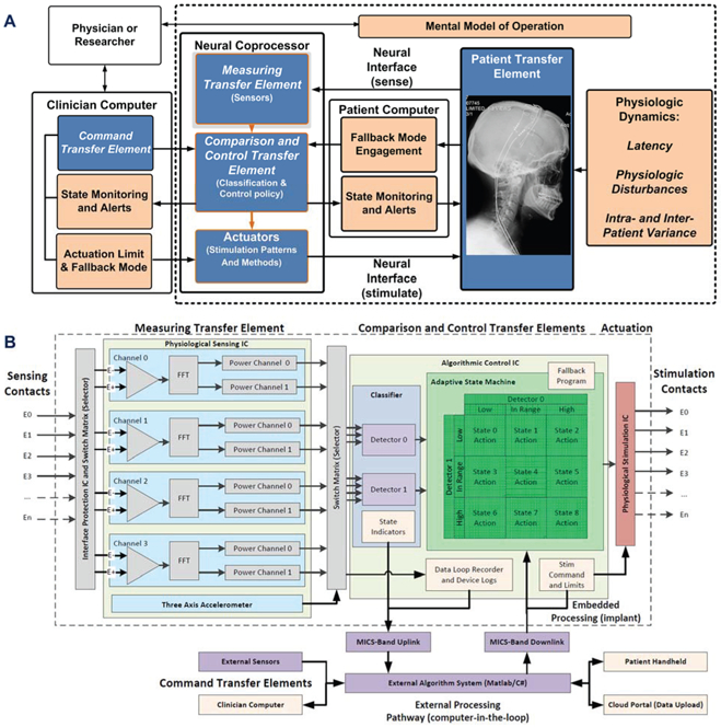
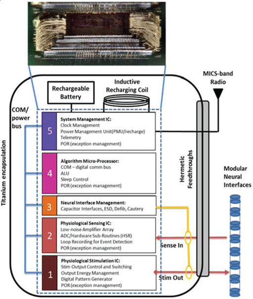
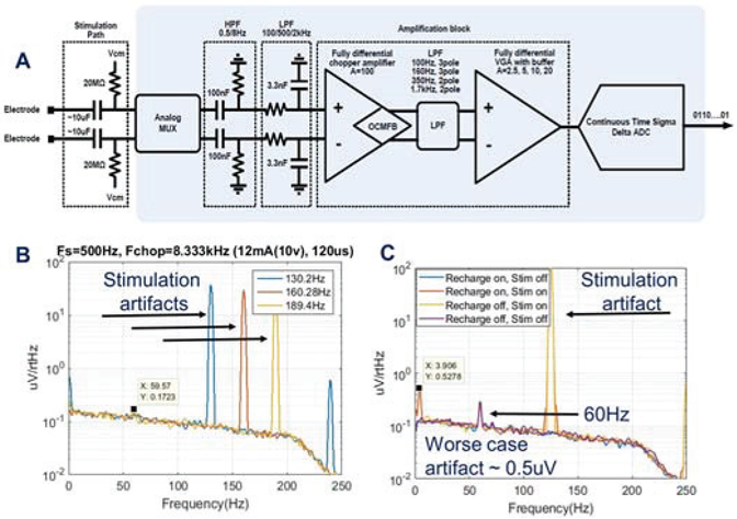
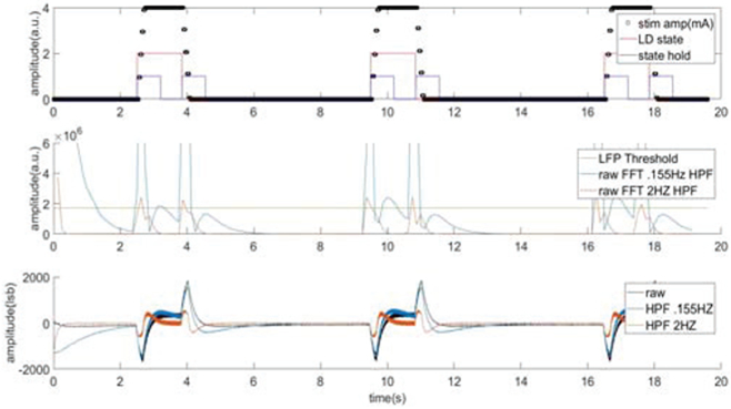
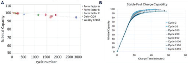
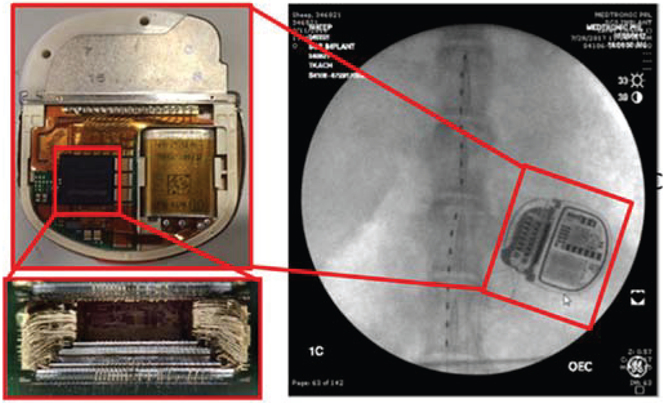
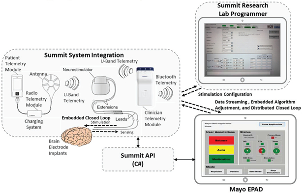
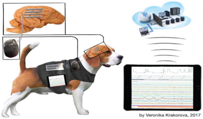
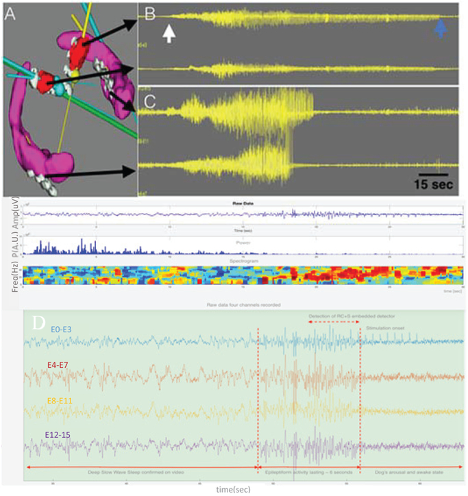
Developing new tools to better understand disorders of the nervous system, with a goal to more effectively treat them, is an active area of bioelectronic medicine research. Future tools must be flexible and configurable, given the evolving understanding of both neuromodulation mechanisms and how to configure a system for optimal clinical outcomes. We describe a system, the Summit RC+S "neural coprocessor," that attempts to bring the capability and flexibility of a microprocessor to a prosthesis embedded within the nervous system. This paper describes the updated system architecture for the Summit RC+S system, the five custom integrated circuits required for bi-directional neural interfacing, the supporting firmware/software ecosystem, and the verification and validation activities to prepare for human implantation. Emphasis is placed on design changes motivated by experience with the CE-marked Activa PC+S research tool; specifically, enhancement of sense-stim performance for improved bi-directional communication to the nervous system, implementation of rechargeable technology to extend device longevity, and application of MICS-band telemetry for algorithm development and data management. The technology was validated in a chronic treatment paradigm for canines with naturally occurring epilepsy, including free ambulation in the home environment, which represents a typical use case for future human protocols.


Figures

Figure 1:
Figure 1:
A representative neural co-processor application. Panel A represents a resting state with implanted depth and cortical leads. Panel B represents the intention to begin pouring drink detected on the cortical sensing lead. Panel C illustrates stimulation turning on and successfully pouring. Panel D returning to rest. Fully embedded cortical sensing movement-related beta desynchronization being utilized to control sub-cortical thalamic stimulation in an essential tremor subject. Note that as the patient moves (highlighted in green), the low frequency signals desynchronize around 20Hz, and the stimulation amplitude increases [9].
Figure 2:
Figure 2:
Functional block diagram of the neural co-processor using the IEC 60601-1-10 framework for a physiologic control system, including explicit terminology for key functional blocks and risk mitigations. A) system functionality is partitioned within the internal neural co-processor, including sensing, algorithm and stimulation blocks, and the external support system for configuring the device. Key functional blocks are in blue, with risk mitigation blocks in tan. B) the reduction of the abstracted system diagram to specific functional blocks in the Summit™ RC+S system signal pathway, including key circuit partitioning, embedded and external processing pathways, and risk mitigation blocks.
Figure 3:
Figure 3:
Mapping the neural coprocessor block diagram into an integrated circuit die stack comprising five custom integrated circuits. Each modular function uses an optimal circuit technology: for example, ICs 1 and 5 use .8μm HV CMOS for stimulation and analog infrastructure, IC 2 uses a 0.25μm CMOS process for sensing and digital signal processing, IC 4 uses a .25μm flash process for micro processing and digital signal processing, and IC block 3 uses a proprietary process for interface protection. The telemetry module is a stand-alone module.
Figure 4:
Figure 4:
Bench-top evaluation of recharge techniques in a saline tank. This plot illustrates optimizing the active recharge ratio to both minimize peak to peak artifact with stim on, and also optimize the stim off step response.
Figure 5:
Figure 5:
A) Block-diagram of the sensing signal chain [note that the 100nF and 3.3nF differentially-matched capacitors are in the passive array] B) sense-stimulation interactions with various frequencies C addition of recharge energy during sensing and stimulation for assessing worst-case artifacts.
Figure 6:
Figure 6:
Evaluation of the impact of adding digital high pass filtering prior to FFT to remove DC offset and improve step response performance.
Figure 7:
Figure 7:
Summary of typical battery characteristics: A) capacity versus cycle number B) capacity versus time for recharging: the impact of stimulation cycles is also represented.
Figure 8:
Figure 8:
Integration of the integrated circuit stack into a final implantable pulse generator, which leverages the Intellis™ system 13.7 cc titanium case and 2×8 connector block. The connectors allow for modular lead connections to a variety of electrode configurations; the example shown is for a spinal cord stimulator in an ovine model.
Figure 9:
Figure 9:
System level of the Summit™ RC+S system including integration of the application-programming-interface for configuring data streaming and algorithmic control of the device, using an example from the Mayo Clinic’s NIH BRAIN initiative program. The Research lab programmer configures the clinician limits for stimulation, and the patient telemetry modules and Epilepsy Personal Assistance Device (EPAD) allow for state monitoring and initiating fallback modes, all per 60601-1-10 guidelines.
Figure 10:
Figure 10:
Illustration of brain coprocessor events from chronic brain recordings in-vivo: events are collected using the on-chip detection algorithms to trigger the detector when seizure-like activity is seen. [29, 32]
Figure 11:
Figure 11:
Bilateral ATN and HC targets and intracranial EEG. A) Bilateral HC (purple) and ATN (red) target volumes and electrodes (gray). Multiple electrodes are in each target. B & C) Four channels of EEG. From top to bottom: Left ATN, Right ATN, Left HC, and Right HC recordings. The white arrow marks the onset of a seizure and the blue the seizure offset. The seizure is seen in all the electrodes, but interestingly the seizure terminates in all electrodes at different times. The longest seizure discharge is in the left ATN. ATN=anterior thalamic nucleus. HC=hippocampus. D) Detection of interictal epileptiform activity longer than 1 second (embedded detector). Onset of the activity is marked together with onset of stimulation with delay about a second. The dog arouses from deep sleep to awake (confirmed on video).

References

    1. Salanova Vicenta et al. “Long-term efficacy and safety of thalamic stimulation for drug-resistant partial epilepsy”, Neurology. 2015. March 10; 84(10): 1017–1025. - PMC - PubMed
    1. Perestelo-Pérez L, et al. “Deep brain stimulation in Parkinson’s disease: meta-analysis of randomized controlled trials. J Neurol 2014; February 2. - PubMed
    1. Schuurman PR, et al. “A comparison of continuous thalamic stimulation and thalamotomy for suppression of severe tremor“ N Engl J Med 2000. February 17;342(7):461–8. - PubMed
    1. Sprengers M et al. “Deep brain and cortical stimulation for epilepsy”, Cochrane Database Syst Rev 2017. July 18;7:CD008497. - PMC - PubMed
    1. Famm K et al. “Drug discovery: a jump-start for electroceuticals”, Nature. 2013. April 11;496(7444): 159–61. - PMC - PubMed

Publication types