. 2018 Jun 29;9(7):330.
doi: 10.3390/mi9070330.

Simulation and Experiment on Droplet Formation and Separation for Needle-Type Micro-Liquid Jetting Dispenser

Affiliations

Simulation and Experiment on Droplet Formation and Separation for Needle-Type Micro-Liquid Jetting Dispenser

Shizhou Lu et al. Micromachines (Basel). .

Abstract

The needle-type droplet jetting dispenser has wide applications in the field of microelectronic packaging, and for which the good quality of droplet formation and separation is the key to successful dispensing. This paper simulates the droplet jetting process which has been divided into 5 stages named backflow, growth, droplet extension, breakage, and separation, and analyses the combined effects of system parameters, such as pressure, viscosity, needle stroke, and nozzle diameter, on the changes of morphologies of ejected droplets, which is verified by experiments. The simulation and experiment results show that a higher driving pressure is quite suitable for the high-viscosity liquid to form normal droplets by avoiding adhesion. When increasing the needle stroke, the pressure should also be lowered properly to prevent the flow-stream. Besides, the nozzle with a large diameter is much more likely to cause sputtering or satellite-droplet problems. The results have a great significance for guiding the parameter settings of the needle-type dispensing approach.

Keywords: droplet; needle-type; non-contact dispensing; piezoelectric actuator.


Conflict of interest statement

The authors declare no conflict of interest.

Figures
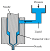
Figure 1
Figure 1
Principle of needle-driven type micro-injection.
Figure 2
Figure 2
The simulation models: (a) gambit mesh model; (b) computational fluid dynamics (CFD) simulation model.
Figure 3
Figure 3
The droplet morphologies in a jetting cycle under the needle vibration: (a) start; (b) backflow; (c) growth; (d) extension; (e) maximum; (f) constriction; (g) breakage; (h) separation.
Figure 4
Figure 4
Dispense failure situation: (a) excessive back suction; (b) adhesion; (c) flow-stream; (d) satellite droplets; (e) sputtering.
Figure 5
Figure 5
Simulation results from changes in viscosity.
Figure 6
Figure 6
Simulation results from changes in pressure when viscosity is (a) 1000 mPa·s; (b) 100 mPa·s.
Figure 7
Figure 7
The combined effects of pressure and viscosity on droplet formation and separation process based on numerical simulations. The symbols, “●” indicates droplet, “▲” indicates adhesion, “■” indicates sputtering, represent experimental results. The experimental parameters are set as: nozzle diameter: 0.2 mm, length: 2 mm, needle stroke: 0.3 mm, frequency: 20 Hz.
Figure 8
Figure 8
Simulation results from the changes in needle stroke when pressure is (a) 0.6 MPa; (b) 0.8 MPa; (c) 0.3 MPa.
Figure 9
Figure 9
The combined effects of pressure and needle stroke on droplet formation and separation process based on numerical simulations. The symbols represent experimental results: “●” indicates droplet, “▲” indicates adhesion, “□” indicates flow-stream. The experimental parameters are set as: viscosity: 800 mPa·s, nozzle diameter: 0.2 mm, length: 2 mm, needle cycle: 20 Hz.
Figure 10
Figure 10
Simulation results from changes in nozzle diameter when stroke is (a) 0.1 mm; (b) 0.3 mm; (c) 0.4 mm.
Figure 11
Figure 11
The combined effects of nozzle diameter and needle stroke on droplet formation and separation process based on numerical simulations. The symbols represent experimental results: “●” indicates droplet, “□” indicates flow-stream, “■” indicates sputtering. The experimental parameters are set as: viscosity: 800 mPa·s, nozzle length: 2 mm, driving pressure: 0.6 MPa, needle cycle: 20 Hz.
Figure 12
Figure 12
The schematic of the jetting experimental system.
Figure 13
Figure 13
(a) Jetting dispenser; (b) Rhombic displacement amplifying mechanism; the black Figure is the state when the piezoelectric actuator is not energized, and the red figure is the state when the piezoelectric actuator is energized; “x” is half of the displacement produced by this piezoelectric actuator; “y” is the stroke of needle.
Figure 14
Figure 14
Viscosity and temperature characteristic curve of the epoxy glue.
Figure 15
Figure 15
Jetting failure situations: (a) adhesion; (b) flow-stream; (c) sputtering; (d) satellite droplets.

References

    1. Chen Y., Li H.X., Shan X., Gao J., Chen X., Wang F. Ultrasound aided smooth dispensing for high viscoelastic epoxy in microelectronic packaging. Ultrason. Sonochem. 2016;28:15–20. doi: 10.1016/j.ultsonch.2015.06.026. - DOI - PubMed
    1. Yao Y.F., Lu S.Z., Liu Y.X., Sun L.N. Research on automated micro-liquid dispensing technology. J. Mech. Eng. 2013;14:140–153. doi: 10.3901/JME.2013.14.140. - DOI
    1. Jeon J., Hong S., Choi M., Choi S. Design and performance evaluation of a new jetting dispenser system using two piezostack actuators. Smart Mater. Struct. 2015;24:11. doi: 10.1088/0964-1726/24/1/015020. - DOI
    1. Urano M., Sakata T., Shimamura T., Ishii H., Chino M., Shimada T., Tazawa H., Machida K. Novel Packaging Technology for Microelectromechanical-System Devices. Jpn. J. Appl. Phys. Part 1. 2005;44:8177–8181. doi: 10.1143/JJAP.44.8177. - DOI
    1. Kumagai K., Fuchiwaki O. A Development of Dispenser for High-Viscosity Liquid and Pick and Place of Micro Objects Using Capillary Force. Key Eng. Mater. 2012;516:48–53. doi: 10.4028/www.scientific.net/KEM.516.48. - DOI

LinkOut - more resources