

An FPGA-Based Backend System for Intravascular Photoacoustic and Ultrasound Imaging
- PMID: 30442605
- PMCID: PMC6384193
- DOI: 10.1109/TUFFC.2018.2881409
An FPGA-Based Backend System for Intravascular Photoacoustic and Ultrasound Imaging
Abstract
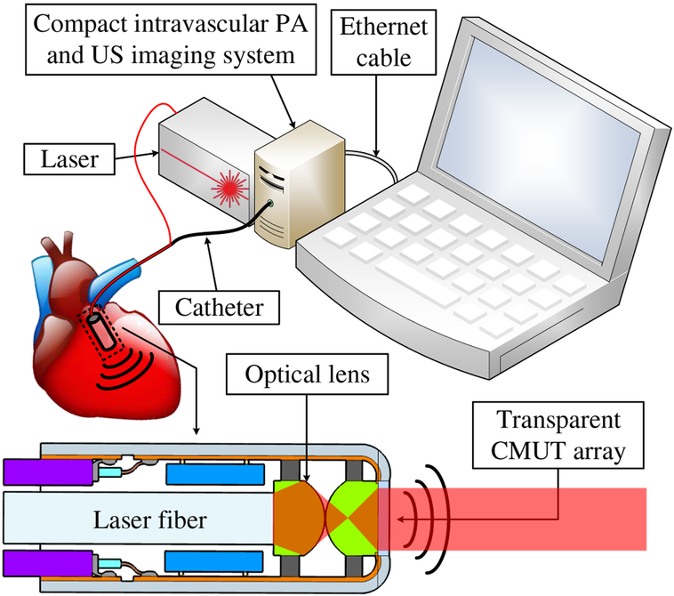
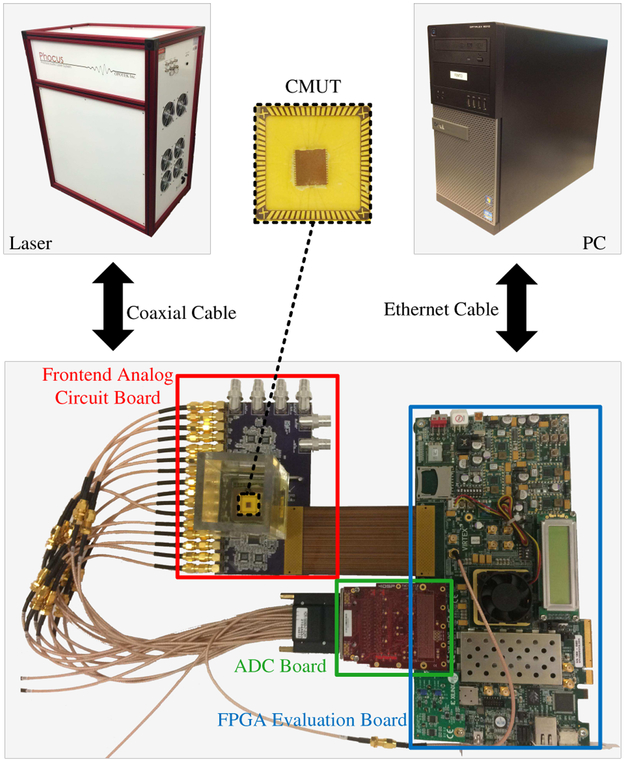
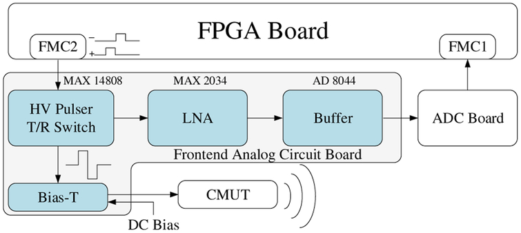
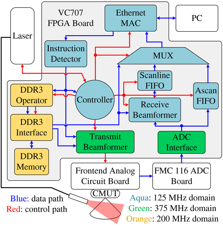
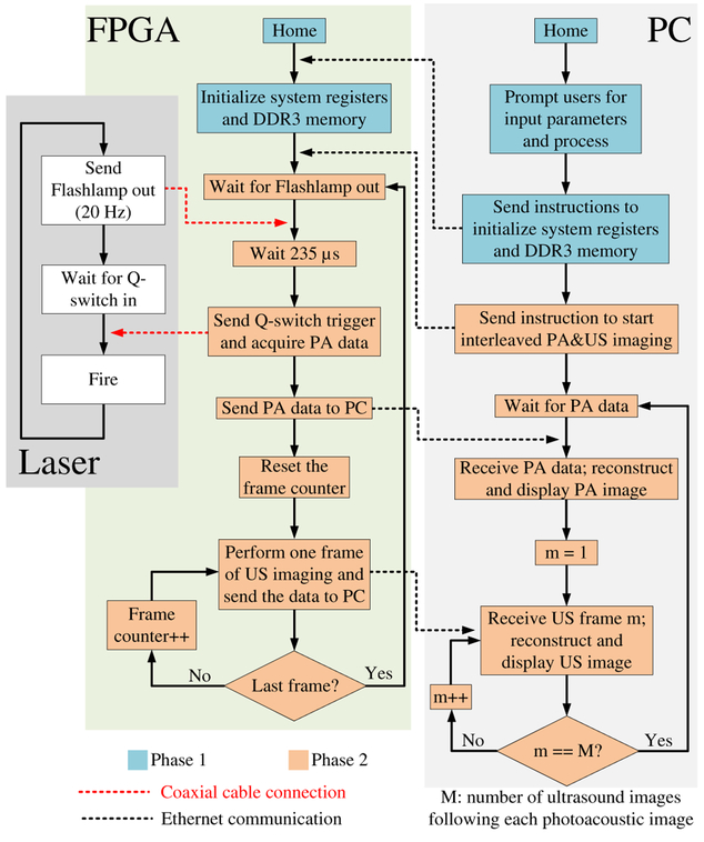
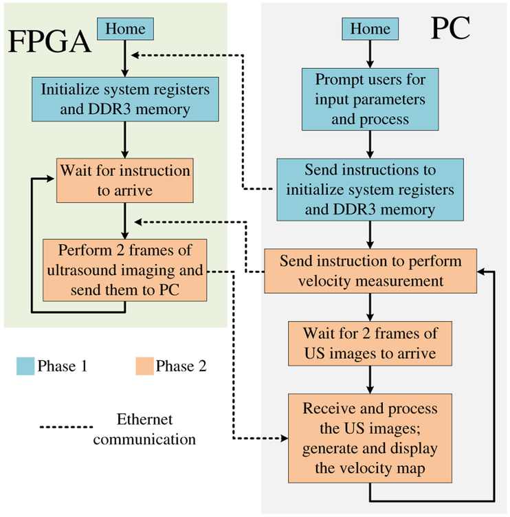
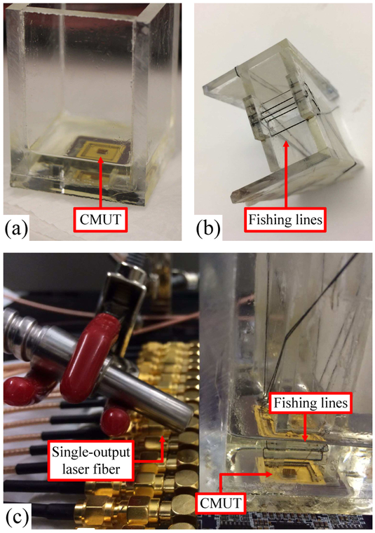
The integration of intravascular ultrasound (IVUS) and intravascular photoacoustic (IVPA) imaging produces an imaging modality with high sensitivity and specificity which is particularly needed in interventional cardiology. Conventional side-looking IVUS imaging with a single-element ultrasound (US) transducer lacks forward-viewing capability, which limits the application of this imaging mode in intravascular intervention guidance, Doppler-based flow measurement, and visualization of nearly, or totally blocked arteries. For both side-looking and forward-looking imaging, the necessity to mechanically scan the US transducer limits the imaging frame rate, and therefore, array-based solutions are desired. In this paper, we present a low-cost, compact, high-speed, and programmable imaging system based on a field-programmable gate array suitable for dual-mode forward-looking IVUS/IVPA imaging. The system has 16 US transmit and receive channels and functions in multiple modes including interleaved photoacoustic (PA) and US imaging, hardware-based high-frame-rate US imaging, software-driven US imaging, and velocity measurement. The system is implemented in the register-transfer level, and the central system controller is implemented as a finite-state machine. The system was tested with a capacitive micromachined ultrasonic transducer array. A 170-frames-per-second (FPS) US imaging frame rate is achieved in the hardware-based high-frame-rate US imaging mode while the interleaved PA and US imaging mode operates at a 60-FPS US and a laser-limited 20-FPS PA imaging frame rate. The performance of the system benefits from the flexibility and efficiency provided by the low-level implementation. The resulting system provides a convenient backend platform for research and clinical IVPA and IVUS imaging.
Figures
References
-
- Nissen SE and Yock P, “Intravascular ultrasound: novel pathophysiological insights and current clinical applications,” Circulation, vol. 103, no. 4, pp. 604–616, 2001. - PubMed
-
- Garcia-Garcia HM, Costa MA, and Serruys PW, “Imaging of coronary atherosclerosis: intravascular ultrasound,” European Heart Journal, vol. 31, no. 20, pp. 2456–2469, 2010. - PubMed
-
- Tobis JM, Mallery J, Mahon D, Lehmann K, Zalesky P, Griffith J, Gessert J, Moriuchi M, McRae M, and Dwyer M-L, “Intravascular ultrasound imaging of human coronary arteries in vivo. analysis of tissue characterizations with comparison to in vitro histological specimens.” Circulation, vol. 83, no. 3, pp. 913–926, 1991. - PubMed
-
- Alfonso F, Macaya C, Goicolea J, Hernandez R, Zamorano J, Perez-Vizcayne MJ, Zarco P et al., “Intravascular ultrasound imaging of angiographically normal coronary segments in patients with coronary artery disease,” American Heart Journal, vol. 127, no. 3, pp. 536–544, 1994. - PubMed
-
- Schumacher M, Yin L, Swaid S, Oldenburger J, Gilsbach J, and Hetzel A, “Intravascular ultrasound Doppler measurement of blood flow velocity,” Journal of Neuroimaging, vol. 11, no. 3, pp. 248–252, 2001. - PubMed
Publication types
MeSH terms
Grants and funding
LinkOut - more resources
Full Text Sources
Miscellaneous
