. 2018 Dec 12;10(49):42030-42038.
doi: 10.1021/acsami.8b15619. Epub 2018 Nov 29.

Implanted Battery-Free Direct-Current Micro-Power Supply from in Vivo Breath Energy Harvesting

Affiliations

Implanted Battery-Free Direct-Current Micro-Power Supply from in Vivo Breath Energy Harvesting

Jun Li et al. ACS Appl Mater Interfaces. .

Abstract

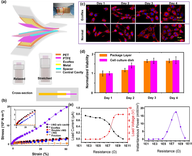
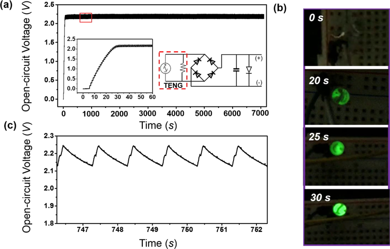
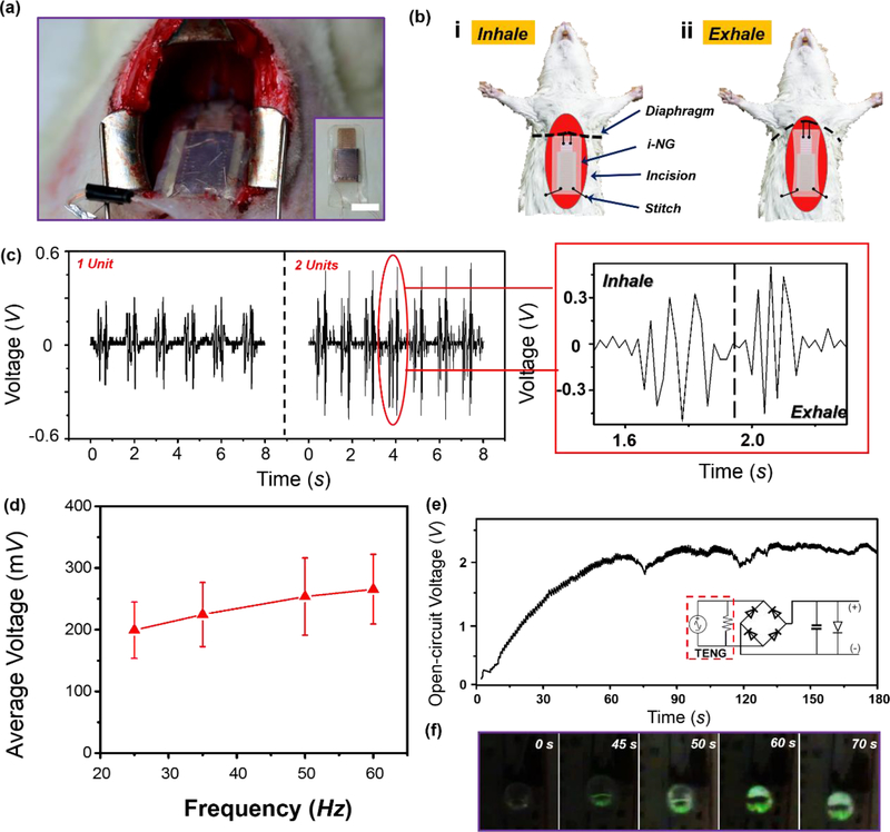
In vivo biomechanical energy harvesting by implanted nanogenerators (i-NGs) is promising for self-powered implantable medical devices (IMDs). One critical challenge to reach practical applications is the requirement of continuous direct-current (dc) output, while the low-frequency body activities typically generate discrete electrical pulses. Here, we developed an ultrastretchable micrograting i-NG system that could function as a battery-free dc micro-power supply. Packaged by a soft silicone elastomer with a cavity design, the i-NG exhibited an ultralow Young's modulus of ∼45 kPa and a high biocompatibility to soft biological tissues. The i-NG was implanted inside the abdominal cavity of Sprague Dawley adult rats and directly converted the slow diaphragm movement during normal respiration into a high-frequency alternative current electrical output, which was readily transmitted into a continuous ∼2.2 V dc output after being integrated with a basic electrical circuit. A light-emitting diode was constantly operated by the breath-driven i-NG without the aid of any battery component. This solely biomechanical energy-driven dc micro-power supply offers a promising solution for the development of self-powered IMDs.

Keywords: battery-free system; direct-current micro-power source; energy harvesting from respiration; implantable medical devices; implantable nanogenerator.


Conflict of interest statement

The authors declare no competing interests.

Figures

Figure 1.
Figure 1.. Nanogenerator design and electrical output characterization.
(a) Schematic diagram showing the in-plane sliding mode of a triboelectric nanogenerator. Middle inset is an SEM image of the nanostructured PTFE surface. Scale bar is 1 μm. Left and right insets show the electrode design and geometric parameters. (b, c) Voltage (b) and short-circuit current (c) outputs of the triboelectric nanogenerator with different electrode finger widths, when they were stretched to the same displacement of 4 mm at 1 Hz frequency. (d) Enlarged current output profiles during one sliding cycle. (e) Voltage measured on a 0.1 μF capacitor when charged by the four different NGs.
Figure 2.
Figure 2.. I-NG design and characterization.
(a) Schematic diagram showing the packaging configuration of an i-NG. Inset is a digital image of a packaged i-NG that was stretch. The scale bar is 1 cm. (b) Strain and stress curves of i-NG without central cavity design (violet hexagon), pure Ecoflex material (black squares), i-NG devices with double triboelectric unit (red triangles) and single unit (blue dots), and an unpackaged triboelectric pair (orange diamonds). The inset is an enlarged figure of curves concentrated at lower stress. (c) Fluorescence microscope image of 3T3 fibroblast cells stained by Texas red-X phalloidin and Hoechst. (d) Cell viability as a function of time. Cells were cultured on the surface of Ecoflex layer as the experimental group and on a culture dish as the control group. (e) Left panel is output voltage and current dependence of i-NG on the load resistance at a frequency of 1 Hz and at low driven speed of 4 cm/s. Right panel is calculated instantaneous output power with respect to the resistance load
Figure 3.
Figure 3.. In Vitro power generating performance.
(a) Long-term open-circuit potential recorded at a green LED load powered by a packaged i-NG. Left inset: The first one-minute charging curve on the LED load; Right inset: Schematic circuit design. (b) A series of images recorded on the LED showing the lighting process as the voltage building up. (c) Zoomed in voltage profile at the flat region in the red box in (a).
Figure 4.
Figure 4.. In vivo biomechanical energy harvesting and powering performance.
(a) A digital image of i-NG implanted inside the abdominal cavity of a SD rat. The inset is the image of the i-NG device. Scale bar is 1 cm. (b) Working process of the i-NG driven by diaphragm motion during respiration. (c) In vivo voltage outputs measured from i-NGs with single unit (left) and double unit (right). Right panel is an enlarged voltage output profile within one inhale-exhale cycle. (d) Average in vivo voltage output as a function of rat respiration frequency (n = 3). (e) The voltage measured at the LED load as a function of time driven by rat respiration. (f) A series of images recorded on the LED showing the lighting process as the in vivo voltage building up.

Similar articles

Cited by

References

    1. Goldberger Z; Lampert R, Implantable Cardioverter-defibrillators: Expanding Indications and Technologies. Jama 2006, 295, 809–818. - PubMed
    1. Goldstein D; Oz M; Rose E, Medical Progress: Implantable Left Ventricular Assist Devices 1522. New England Journal of Medicine-Unbound Volume 1998, 339. - PubMed
    1. Navarro M; Michiardi A; Castano O; Planell J, Biomaterials in Orthopaedics. Journal of the Royal Society Interface 2008, 5, 1137–1158. - PMC - PubMed
    1. Amar AB; Kouki AB; Cao H, Power Approaches for Implantable Medical Devices. Sensors 2015, 15, 28889–28914. - PMC - PubMed
    1. Bock DC; Marschilok AC; Takeuchi KJ; Takeuchi ES, Batteries Used to Power Implantable Biomedical Devices. Electrochimica acta 2012, 84, 155–164. - PMC - PubMed