Review
. 2018 Nov 5:12:68.
doi: 10.3389/fninf.2018.00068. eCollection 2018.

Code Generation in Computational Neuroscience: A Review of Tools and Techniques

Affiliations
Review

Code Generation in Computational Neuroscience: A Review of Tools and Techniques

Inga Blundell et al. Front Neuroinform. .

Abstract

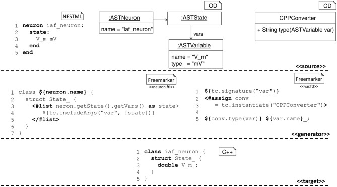
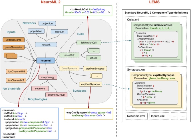
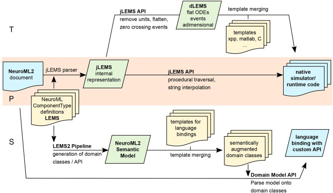
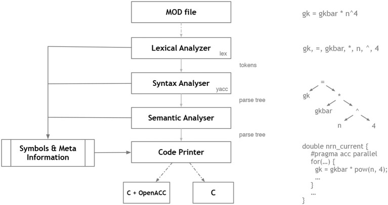
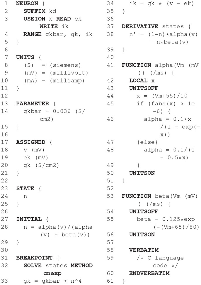
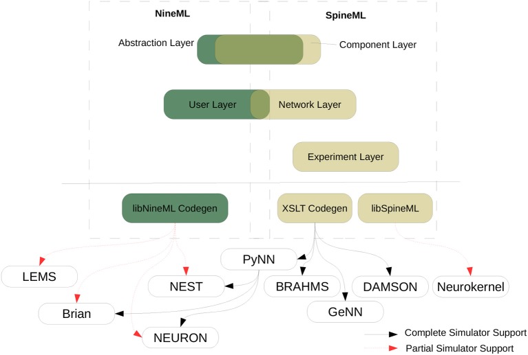
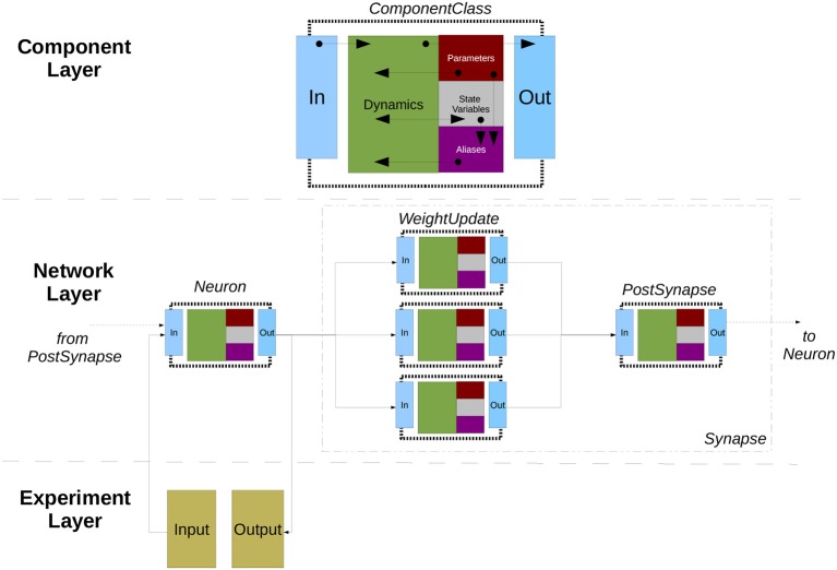
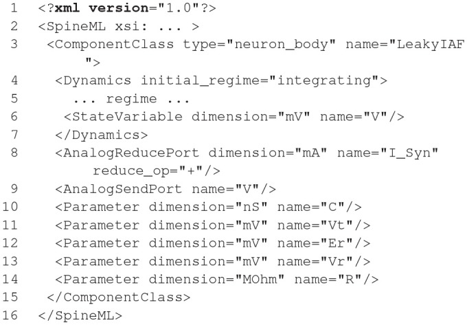
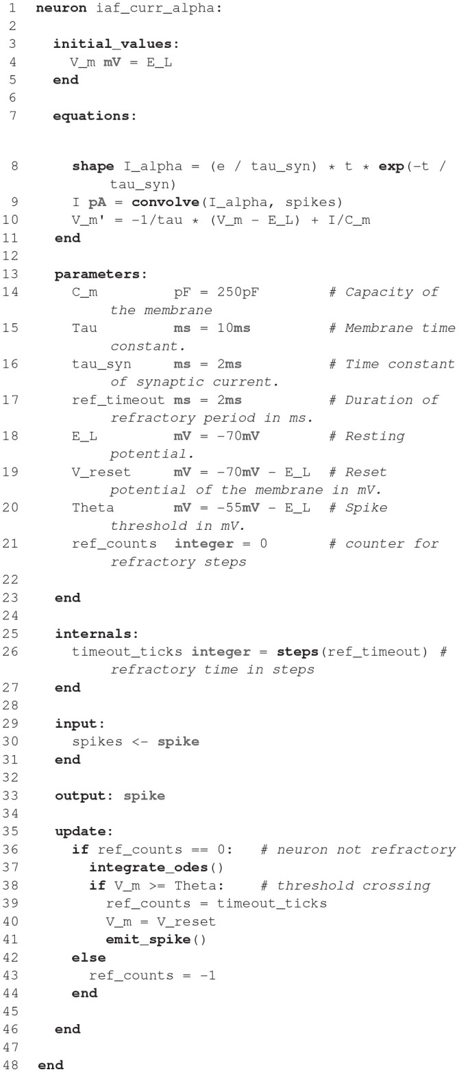
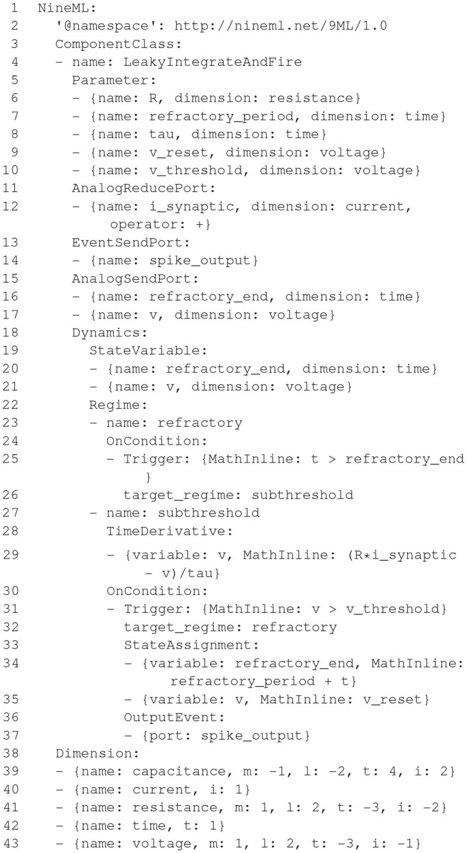
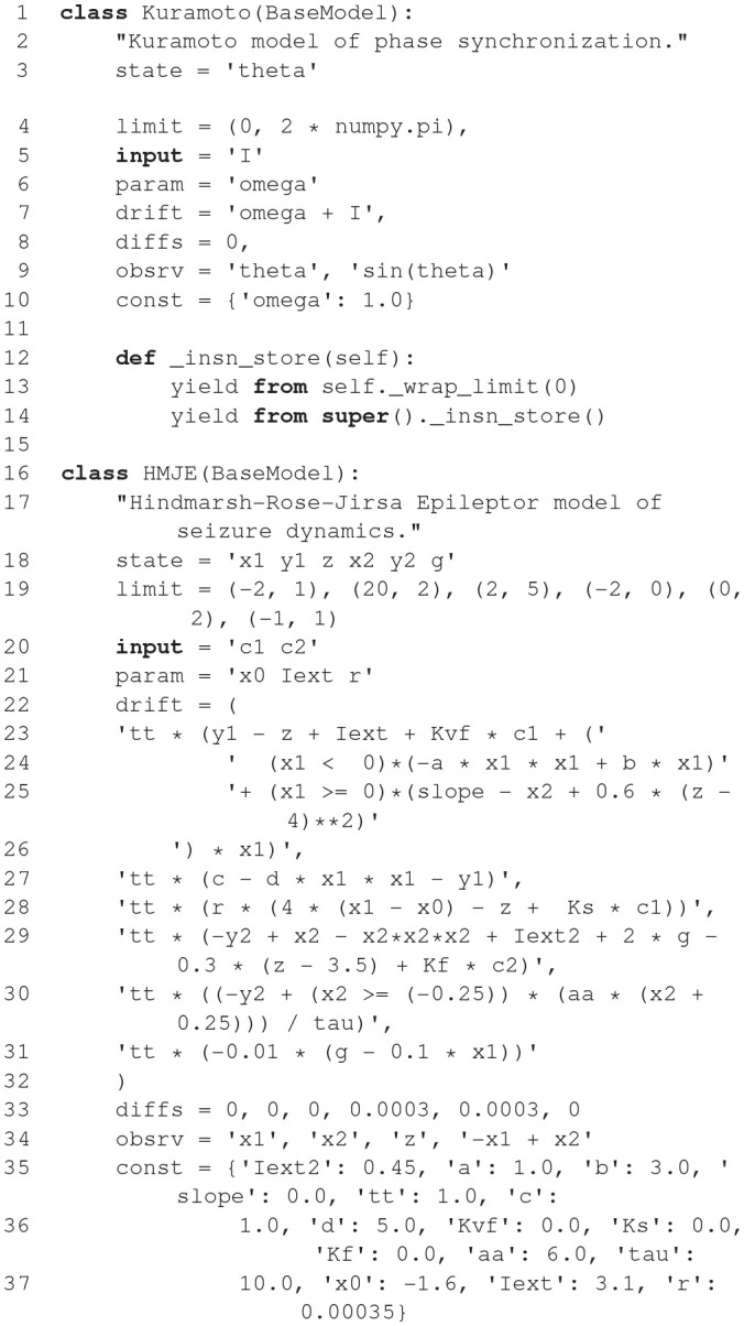
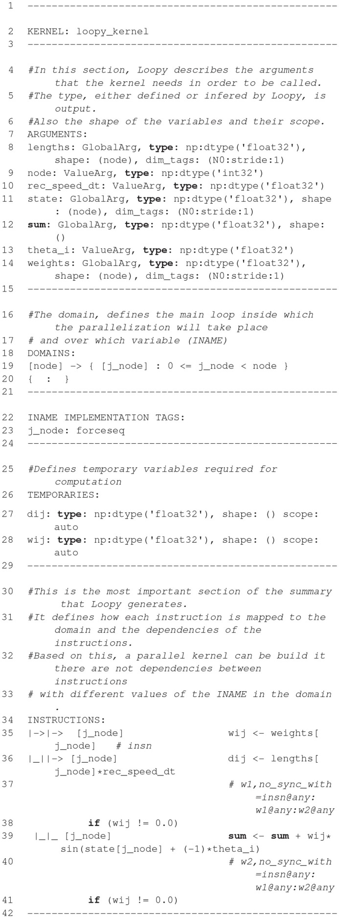
Advances in experimental techniques and computational power allowing researchers to gather anatomical and electrophysiological data at unprecedented levels of detail have fostered the development of increasingly complex models in computational neuroscience. Large-scale, biophysically detailed cell models pose a particular set of computational challenges, and this has led to the development of a number of domain-specific simulators. At the other level of detail, the ever growing variety of point neuron models increases the implementation barrier even for those based on the relatively simple integrate-and-fire neuron model. Independently of the model complexity, all modeling methods crucially depend on an efficient and accurate transformation of mathematical model descriptions into efficiently executable code. Neuroscientists usually publish model descriptions in terms of the mathematical equations underlying them. However, actually simulating them requires they be translated into code. This can cause problems because errors may be introduced if this process is carried out by hand, and code written by neuroscientists may not be very computationally efficient. Furthermore, the translated code might be generated for different hardware platforms, operating system variants or even written in different languages and thus cannot easily be combined or even compared. Two main approaches to addressing this issues have been followed. The first is to limit users to a fixed set of optimized models, which limits flexibility. The second is to allow model definitions in a high level interpreted language, although this may limit performance. Recently, a third approach has become increasingly popular: using code generation to automatically translate high level descriptions into efficient low level code to combine the best of previous approaches. This approach also greatly enriches efforts to standardize simulator-independent model description languages. In the past few years, a number of code generation pipelines have been developed in the computational neuroscience community, which differ considerably in aim, scope and functionality. This article provides an overview of existing pipelines currently used within the community and contrasts their capabilities and the technologies and concepts behind them.

Keywords: code generation; domain specific language; modeling language; neuronal networks; simulation.


Figures

Figure 1
Figure 1
Brian model structure. Brian users define models by specifying equations governing a single neuron or synapse. Simulations consist of an ordered sequence of operations (code blocks) acting on neuronal or synaptic data. A neuronal code block can only modify its own data, whereas a synaptic code block can also modify data from its pre- or post-synaptic neurons. Neurons have three code blocks: one for its continuous evolution (numerical integration), one for checking threshold conditions and emitting spike events, and one for post-spike reset in response to those events. Synapses have three code blocks: two event-based blocks for responding to pre- or postsynaptic spikes (corresponding to forward or backward propagation), and one continuous evolution block. Code blocks can be provided directly, or can be generated from pseudo-code or differential equations.
Figure 2
Figure 2
Brian code generation pipeline. Code is transformed in multiple stages: the original Brian code (in Python), with a differential equation given in standard mathematical form; the internal pseudocode or “abstract code” representation (Python syntax), in this case an exact numerical solver for the equations; the C++ code snippets generated from the abstract code; the compilable C++ code. Note that the C++ code snippets include a scalar and vector part, which is automatically computed from the abstract code. In this case, a constant has been pulled out of the loop and named _lio_1.
Figure 3
Figure 3
Schematic of the code generation flow for the GPU simulator framework GeNN. Neural models are described in a C/C++ model definition function (“ExampleModel.cc”), either hand-crafted by a user or generated from a higher-level model description language such as SpineML or Brian 2 (see main text). The neuron model description is included into the GeNN compiler that produces optimized CUDA/C++ code for simulating the specified model. The generated code can then be used by hand-crafted or independently generated user code to form the final executable. The framework is minimalistic in generating only optimized CUDA/C++ code for the core model and not the simulation workflow in order to allow maximal flexibility in the deployment of the final executable. This can include exploratory or large scale simulations but also real-time execution on embedded systems for robotics applications. User code in blue, GeNN components in gray, generated CUDA/C++ code in pink.
Figure 4
Figure 4
Example definition of a NESTML concept and generation of the AST. (Left) A production for a function in NESTML. The lefthandside defines the name of the production, the righthandside defines the production using terminals, other productions and special operators (*, ?). A function starts with the keyword function followed by the function's name and an optional list of parameters enclosed in parentheses followed by the optional return value. Optional parts are marked with ?. The function body is specified by the production (Block) between two keywords. (Right) The corresponding automatically derived meta-model as a class diagram. Every production is mapped to an AST class, which is used in the further language processing steps.
Figure 5
Figure 5
Components for the code generation in NESTML. (Top) Source model, corresponding AST, and helper classes. (Middle) Templates for the generation of C++ code. The left template creates a C++ class body with an embedded C++ struct, the right template maps variable name and variable type using a helper class. The template on the left includes the template on the right once for each state variable defined in the source model. (Bottom) A C++ implementation as created from the source model using the generation templates.
Figure 6
Figure 6
NeuroML2 and LEMS. NeuroML2 is a language which defines a hierarchical set of elements used in computational models in neuroscience in the following broad categories: Networks, Cells, Synapses, Morphologies, Ion Channels, and Inputs. These provide the building blocks for specifying 3D populations of cells, both morphologically detailed and abstract, connected via a variety of (plastic) chemical and electrical synapses receiving external spike or current based stimuli. Examples are shown of the (truncated) XML representations of: (blue) a network containing two populations of integrate-and-fire cells connected by a single projection between them; (green) a spiking neuron model as described by Izhikevich (2003); (yellow) a conductance based synapse with a single exponential decay waveform. On the right the definition of the structure and dynamics of these elements in the LEMS language is shown. Each element has a corresponding ComponentType definition, describing the parameters (as well as their dimensions, not shown) and the dynamics in terms of the state variables, the time derivative of these, any derived variables, and the behavior when certain conditions are met or (spiking) events are received. The standard set of ComponentType definitions for the core NeuroML2 elements are contained in a curated set of files (Cells.xml, Synapses.xml, etc.) though users are free to define their own ComponentTypes to extend the scope of the language.
Figure 7
Figure 7
Multiple pipelines involving code generation for NeuroML2 and LEMS. Purely Procedural (P) and intermediate representation/Template-based (T) pipelines, both stemming from the internal representation constructed by jLEMS from parsed LEMS XML documents. S: Generation of customizable language bindings via construction of LEMS Semantic model and merging with templates.
Figure 8
Figure 8
NMODL code generation workflow in NEURON/CoreNEURON targeting CPU/GPU.
Listing 1
Listing 1
NMODL example of voltage-gated potassium current.
Figure 9
Figure 9
A comparison of the SpineML and NineML specification. The SpineML syntax is a proposed extension to the NineML modeling format which provides a complete syntax for describing models of spiking point neuron models with varying biological complexity. The SpineML syntax extends NineML and allows full simulator support for all three layers of components, networks and experiments (Adapted from Richmond et al., 2014).
Figure 10
Figure 10
The modular dynamics within the three layers of SpineML. The figure shows the connectivity of a Neuron and Synapse, including WeightUpdates and a PostSynapse model. A ComponentClass described within the component layer defines the dynamical behavior of neurons, synapses, and neuromodulators. A ComponentClass updates state variables and emits outputs, by evolving differential equations, inputs, and aliases (parameters and state variables). Input and Output ports create an interface which enable each component instance to be connected to other instances within the network layer. The experiment layer defines network inputs such as spike sources or current injections (Taken from Richmond et al., 2014).
Listing 2
Listing 2
A SpineML Component representation of a leaky integrate-and-fire neuron. The definition of regimes has been moved to a separate listing.
Listing 3
Listing 3
Integration regime for a leaky integrate-and-fire neuron.
Figure 11
Figure 11
A tool-chain for simulation through code generation using the SpineML modeling syntax. The SpineML modeling syntax is composed of three layers, structured according to an XML Schema. Models can be generated manually using XML editors or using graphical user interface (GUI) tools. Translation of a model to any simulator is achieved by using a simulator specific set of XSLT templates, or Python libraries, to generate simulator code or native simulator model descriptions. Simulator code then logs results in a standardized format which can be used for plotting and analysis (Adapted from Richmond et al., 2014).
Listing 4
Listing 4
Neurokernel CUDA kernel.
Figure 12
Figure 12
SpiNNaker Python model components. The threshold types govern logic for determining if the neuron should spike given a membrane potential; the synapse type describes how the weight from a synapse changes over time; the input type governs the logic to change from a weight to current; an additional input type allows the addition of more current to a neuron given a membrane potential; the neuron type encapsulates the equations for processing the current and determining the membrane potential at each time step.
Listing 5
Listing 5
The IfCurExp Makefile for SpiNNaker.
Figure 13
Figure 13
The SpiNNaker software flow. The system starts by utilizing a PyNN script, which is then mapped onto SpiNNaker core sized chunks which are placed and routed on the SpiNNaker machine. The neuron parameters, synapse data, and binaries are loaded onto the machine and executed, with host based runtime functionality to support the executing simulation.
Figure 14
Figure 14
Interaction between the different computational stages in a neural mass model simulation. The raw connectivity from sources such as diffusion tensor imaging is pre-processed to produce a connectivity map between brain regions defined by a parcellation scheme. The connectivity map is fed into a network kernel composed of a coupling, neural mass and integration kernel. The coupling kernel combines the simulated system's current state with the connectivity data to compute the input to each node for the current time step. For each node, the NMM kernel computes the state changes which are fed into the integration kernel to compute the final state at the end of the current time step. The resulting observables are fed back to the coupling kernel and forward to a post-processing kernel to compute derived signals such as BOLD or EEG data for comparison to experimental results. Since there are no dependencies between distinct instances of the network kernel, this data flow can be parallelized over each set of model parameters.
None
None
None
None
None
None
None
None
None
None

References

    1. Aamir S. A., Müller P., Kriener L., Kiene G., Schemmel J., Meier K. (2017). From LIF to AdEx neuron models: accelerated analog 65-nm CMOS implementation in IEEE Biomedical Circuits and Systems Conference (BioCAS) (Turin: ). - PubMed
    1. Aho A. V., Lam M. S., Sethi R., Ullman J. D. (2006). Compilers: Principles, Techniques, and Tools, (2nd Edn). Boston, MA: Addison-Wesley Longman Publishing Co., Inc.
    1. ARM Limited (2006). Arm968e-s Technical Reference Manual.
    1. Bhalla U. S., Bower J. M. (1993). Genesis: a neuronal simulation system in Neural Systems: Analysis and Modeling (New York, NY: ), 95–102.
    1. Blundell I., Plotnikov D., Eppler J. M., Morrison A. (2018). Automatically selecting a suitable integration scheme for systems of differential equations in neuron models. Front. Neuroinform. 12:50 10.3389/fninf.2018.00050 - DOI - PMC - PubMed