

Review
doi: 10.1021/acs.analchem.8b05293.
Epub 2018 Dec 11.
Recent Advances in Body-on-a-Chip Systems
Affiliations
- PMID: 30472828
- PMCID: PMC6687466
- DOI: 10.1021/acs.analchem.8b05293
Item in Clipboard
Review
Recent Advances in Body-on-a-Chip Systems
Anal Chem.
.
No abstract available
Conflict of interest statement
Disclosure of Potential Conflict of Interest
The authors confirm that competing financial interests exist but there has been no financial support for this work that could have influenced its outcome. However, JJH and MLS have a potential competing financial interest, in that a company has been formed to market services for types of cells like this in body-on-a-chip devices.
Figures

Applying well-established BOC platforms to a broad range of BOC models. A) A NMJ model based on the microtunnel microscale platform. Reprinted from Biomaterials, Vol. 166, Santhanam, N.; Kumanchik, L.; Guo, X.; Sommerhage, F.; Cai, Y.; Jackson, M.; Martin, C.; Saad, G.; McAleer, C. W.; Wang, Y.; Lavado, A.; Long, C. J.; Hickman, J. J. Stem cell derived phenotypic human neuromuscular junction model for dose response evaluation of therapeutics, pp. 64–78 (ref 10). Copyright 2018, with permission from Elsevier. B) A pancreatic islet-liver model driven by pneumatic an on-chip micropump. Adapted under the terms of the CC-BY-4.0 license. Copyright 2017, the authors. Individual organ modules have also been connected in series to construct BOC systems. C) A neurovascular unit model. Reprinted by permission from Macmillan Publishers Ltd: Nature Biotechnology, Maoz, B. M.; Herland, A.; FitzGerald, E. A.; Grevesse, T.; Vidoudez, C.; Pacheco, A. R.; Sheehy, S. P.; Park, T. E.; Dauth, S.; Mannix, R.; Budnik, N.; Shores, K.; Cho, A.; Nawroth, J. C.; Segre, D.; Budnik, B.; Ingber, D. E.; Parker, K. K. Nat Biotechnol 2018, 36, 865–874 (ref 16). Copyright 2018. D) A multi-tissue system on an integrate plate with fluid circulation driven by electromagnetic actuation to emulate female reproductive tract and the endocrine loops. Adapted under the terms of the CC-BY-4.0 license. Copyright 2017, the authors. Pumpless platforms were adopted to construct a cardiac-liver chip (E) and a whole-body model (F). Panel E was reprinted from Biomaterials 182: 176–190, vol 182, Carlota Oleaga, Anne Riu, Sandra Rothemund, Andrea Lavado, Christopher W. McAleer, Christopher J. Long, Keisha Persaud, Narasimhan Sriram Narasimhan, My Tran, Jeffry Roles, Carlos A. Carmona-Moran, Trevor Sasserath, Daniel H. Elbrecht, Lee Kumanchik, L. Richard Bridges, Candace Martin, Mark T. Schnepper, Gail Ekman, Max Jackson, Ying I. Wang, Reine Note, Jessica Langer, Silvia Teissier, James J. Hickman, Investigation of the effect of hepatic metabolism on off-target cardiotoxicity in a multi-organ human-on-a-chip system (ref 23). Copyright 2018, with permission from Elsevier.

Configurable BOC platforms. A) A hanging drop array-based BOC platform. Neighboring hanging drops are connected with open channels. Hanging drops in each column (1, 2, 3, or 4) are connected in series and loaded with rLi cells (columns 1–3) or with HCT-116 cells (column 4). The fluid network is then reconfigured to support multiorgan culture by filling channels connecting neighboring drops in a row. Reprinted by permission from Macmillan Publishers Ltd: Nature Communications, Frey, O.; Misun, P. M.; Fluri, D. A.; Hengstler, J. G.; Hierlemann, A. Nat Commun
2014, 5, 4250 (ref 29). Copyright 2014. B) A single-pass integrated liver-kidney system. i) Live cells were loaded to the liver chamber using ports 3 and 2; Kidney cells were loaded to the kidney chamber using ports 4 and 5. ii) Liver-kidney co-culture was established by switching to sing-pass perfusion using ports 2 and 5. All ports not in use were blocked. Reproduced from Theobald, J.; Ghanem, A.; Wallisch, P.; Banaeiyan, A. A.; Andrade-Navarro, M. A.; Taškova, K.; Haltmeier, M.; Kurtz, A.; Becker, H.; Reuter, S.; Mrowka, R.; Cheng, X.; Wölfl, S. ACS Biomaterials Science & Engineering
2017, 4, 78–89 (ref 40). Copyright 2017 American Chemical Society. C) A 7-MPS platform driven by pneumatically actuated micropumps. These on-chip individually addressable micropumps allow precise fluid control and differential flow distribution towards different organ modules. Reprinted from Edington, C. D.; Chen, W. L. K.; Geishecker, E.; Kassis, T.; Soenksen, L. R.; Bhushan, B. M.; Freake, D.; Kirschner, J.; Maass, C.; Tsamandouras, N.; Valdez, J.; Cook, C. D.; Parent, T.; Snyder, S.; Yu, J.; Suter, E.; Shockley, M.; Velazquez, J.; Velazquez, J. J.; Stockdale, L., et al. Sci Rep
2018, 8, 4530 (ref 30) under the terms of the Creative Commons Attribution 4.0 International License. Copyright 2018, the authors.

New strategies towards unidirectional perfusion on a pumpless platform. A) A pumpless platform provides unidirectional tissue perfusion for most of the time with transient backflow. Reproduced from A microfluidic chip with gravity-induced unidirectional flow for perfusion cell culture, Lee, D. W.; Choi, N.; Sung, J. H. Biotechnol Prog (ref 36). Copyright 2018 Wiley. B) A pumpless platform provides unidirectional tissue perfusion for a fraction of the cycle and stalled flow for the rest of it. Fluid travels between a pair of reservoirs alternately through the tissue perfusion channel and the bypass channel. Reproduced from Esch, M. B.; Ueno, H.; Applegate, D. R.; Shuler, M. L. Lab Chip
2016, 16, 2719–2729 (ref 27) by permission of The Royal Society of Chemistry. C) UniChip achieves continuous unidirectional perfusion with recirculation in a gravity driven flow system . i) An assembled UniChip device is placed on a rocker platform that flips between +18° and −18° periodically. ii) Top view of the device shows fluidic connections. Cu, perfusion channel; a1, a2, b1, and b2, Supporting channels; v1, v2, passive valves. iii) Schematic of UniChip operation. When tilted at +18°, flow in b1 is halted by the capillary force at the air–liquid interface in the passive valve v1. Flow travels from reservoir I to reservoir II through a1, a2, Cu and b2. When tilted at −18°, flow in b2 is halted by valve v2, and flow is directed from reservoir II to reservoir I through a2, a1, Cu and b1. Under either condition, the flow direction in the perfusion channel, Cu, is kept the same, shown by the green arrows. Adapted from Wang, Y. I.; Shuler, M. L. Lab Chip
2018, 18, 2563–2574 (ref 37) with permission of The Royal Society of Chemistry.

A pneumatic pressure-driven recirculating BOC system. A) Two-step process of medium recirculation in a 2-organ system. B) Exploded view of a culture device with 4 × 4 culture chambers and illustration of a culture chamber at X–X′ cross-section. C) Schematic of the design and function of a “Laplace valve.” D) Illustrations of the culture chamber equipped with a modified transwell insert. Adapted from Satoh, T.; Sugiura, S.; Shin, K.; Onuki-Nagasaki, R.; Ishida, S.; Kikuchi, K.; Kakiki, M.; Kanamori, T. Lab Chip
2017, 18, 115–125 (ref 39) with permission from The Royal Society of Chemistry.

BOC systems with circulating cells. A) A four-chamber BOC system to recapitulate CTC adhesion to endothelial layers in organ-specific metastasis. Reproduced from Kong, J.; Luo, Y.; Jin, D.; An, F.; Zhang, W.; Liu, L.; Li, J.; Fang, S.; Li, X.; Yang, X.; Lin, B.; Liu, T. Oncotarget
2016, 7, 78421–78432 (ref 42) under the terms of the Creative Commons Attribution 3.0 License. Copyright 2016, the authors. B) A lung cancer metastasis model. Reprinted from Xu, Z.; Li, E.; Guo, Z.; Yu, R.; Hao, H.; Xu, Y.; Sun, Z.; Li, X.; Lyu, J.; Wang, Q. ACS Appl Mater Interfaces
2016, 8, 25840–25847 (ref 43). Copyright 2016 American Chemical Society. C) A single-pass microfluidic perfusion model to model the dynamic interactions between tumor infiltration lymphocytes (TILs) and tumor tissues. Adapted from Moore, N.; Doty, D.; Zielstorff, M.; Kariv, I.; Moy, L. Y.; Gimbel, A.; Chevillet, J. R.; Lowry, N.; Santos, J.; Mott, V.; Kratchman, L.; Lau, T.; Addona, G.; Chen, H.; Borenstein, J. T. Lab Chip
2018, 18, 1844–1858 (ref 41) with permission from The Royal Society of Chemistry.

Four multi-organ systems used to demonstrate organ-organ interaction and toxicity to compounds using functional readouts obtained via integrated on-chip sensors. (A) Schematic overview of the microfluidic device and on-chip sensors used by Oleaga et al (2018) to demonstrate real time changes to off target cardiotoxicity due to hepatic metabolism. (organ-organ interaction). The sensors used include silicon cantilevers for cardiac force, microelectrode array for cardiac electrophysiological data. Reprinted from Biomaterials 182: 176–190, vol 182, Carlota Oleaga, Anne Riu, Sandra Rothemund, Andrea Lavado, Christopher W. McAleer, Christopher J. Long, Keisha Persaud, Narasimhan Sriram Narasimhan, My Tran, Jeffry Roles, Carlos A. Carmona-Moran, Trevor Sasserath, Daniel H. Elbrecht, Lee Kumanchik, L. Richard Bridges, Candace Martin, Mark T. Schnepper, Gail Ekman, Max Jackson, Ying I. Wang, Reine Note, Jessica Langer, Silvia Teissier, James J. Hickman, Investigation of the effect of hepatic metabolism on off-target cardiotoxicity in a multi-organ human-on-a-chip system (ref 23). Copyright 2018, with permission from Elsevier. (B) Schematic overview of system and on chip sensors used by Zhang et al (2017) to demonstrate real time drug toxicity in a heart-liver system. An integrated biochemical sensor module was used to measure biomarkers of interest pointing to toxicity. Reproduced from Zhang, Y. S.; Aleman, J.; Shin, S. R.; Kilic, T.; Kim, D.; Mousavi Shaegh, S. A.; Massa, S.; Riahi, R.; Chae, S.; Hu, N.; Avci, H.; Zhang, W.; Silvestri, A.; Sanati Nezhad, A.; Manbohi, A.; De Ferrari, F.; Polini, A.; Calzone, G.; Shaikh, N.; Alerasool, P., et al. Proc Natl Acad Sci U S A
2017, 114, E2293-E2302 (ref 15), with permission from proceedings of the national academy of sciences USA. (C) Schematic overview of a microfluidic system with integrated microelectrode arrays and TEER electrodes to demonstrate the effect of TNF-alpha on vascular endothelium and cardiomyocytes. Reproduced from Maoz, B. M., A. Herland, O. Y. F. Henry, W. D. Leineweber, M. Yadid, J. Doyle, R. Mannix, V. J. Kujala, E. A. FitzGerald, K. K. Parker and D. E. Ingber, Lab Chip 17(13): 2294–2302 (ref 49), with permission of The Royal Society of Chemistry. (D) Schematic overview of multiorgan microfluidic set up with integrated TEER electrodes and optical monitoring of cardiac beating in a heart-liver-lung system. Reproduced under the terms of the CC-BY-4.0 license. Copyright 2017, the authors.
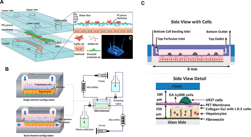
(A) A liver sinusoid model containing hepatocytes, Kupffer cells, stellate cells and sinusoid endothelial cells. Reproduced from Du, Y.; Li, N.; Yang, H.; Luo, C.; Gong, Y.; Tong, C.; Gao, Y.; Lü, S.; Long, M. Lab Chip, 17, 782–794 (ref 72), with permission of The Royal Society of Chemistry. (B) A microfluidic chip with single and dual channel configurations, mimicking the liver sinusoid structure. Reproduced from Liver sinusoid on a chip: Long-term layered co-culture of primary rat hepatocytes and endothelial cells in microfluidic platforms, Kang, Y.B.; Sodunke, T.R.; Lamontagne, J.; Cirillo, J.; Rajiv, C.; Bouchard, M.J..; Noh, M. Biotech. Bioeng., Vol. 112, Issue 12 (ref 73). Copyright 2016 Wiley (C) A two-chambered microfluidic device containing four cell types (hepatocytes, endothelial, stellate, and Kupffer cell lines). Reproduced from Long-term maintenance of a microfluidic 3D human liver sinusoid, Prodanov, L.; Jindal, R.; Bale, S.S.; Hegde, M.; McCarty, W.J.; Golberg, I.; Bhushan, A.; Yarmush, M.L.; Usta, O.B. Biotech. Bioeng., Vol. 113, Issue 1 (ref 74). Copyright 2016 Wiley.
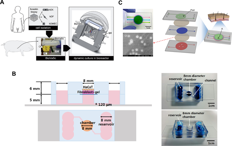
(A) Construction of vascularized skin model using a decellularized segment of porcine jejunum and keratinocytes, fibroblasts, and endothelial cells. Reproduced from Groeber, F.; Engelhardt, L.; Lange, J.; Kurdyn, S.; Schmid, F.F.; Rücker, C.; Mielke, S.; Walles, H.; Hansmann, J., ALTEX, 33, 415–422 (ref 86), under the terms of the Creative Commons Attribution 4.0 International License. Copyright 2016, the authors. (B) A two-layer microfluidic skin chip containing human primary keratinocytes, fibroblasts and HUVEC. Reprinted by permission from Lee, S.; Jin, S.P.; Kim, Y.K.; Sung, G.Y.; Chung, J.H.; Sung, J.H., Biomed Microdev 2017, 19, 22 (ref 87). (C) A microfluidic skin chip with HaCaT, fibroblasts, and HUVEC. Reprinted from Wufuer, M.; Lee, G.; Hur, W.; Jeon, B.; Kim, B. J.; Choi, T. H.; Lee, S. Sci Rep
2016, 6, 37471 (ref 88), under the terms of the Creative Commons Attribution 4.0 International License. Copyright 2016, the authors.

(A) A schematic diagram of gut-liver platform for studying PK of drugs. Reproduced from First pass intestinal and liver metabolism of paracetamol in a microfluidic platform coupled with a mathematical modeling as a means of evaluating ADME processes in humans, Prot J. M.; Maciel L.; Bricks T.; Merlier F.; Cotton J.; Paullier P.; Bois F. Y.; Leclerc E. Biotech. Bioeng., Vol. 111, Issue 10 (ref 111). Copyright 2014 Wiley. (B) A microfluidic 4-organ platform and fluid dynamics simulation showing the levels of shear stress in each compartment. Reprinted from Oleaga, C.; Bernabini, C.; Smith, A. S.; Srinivasan, B.; Jackson, M.; McLamb, W.; Platt V.; Bridges, R.; Cai, Y.; Santhanam, N.; Berry B.; Najjar, S.; Akanda, N.; Guo, X.; Martin, C.;, Ekman, G.; Esch, M. B.; Langer, J.; Ouedraogo, G.; Cotovio, J.; Breton, L.; Shuler, M. L.; Hickman, J. J., Sci Rep 2016, 6, 20030 (ref 25), under the terms of the Creative Commons Attribution 4.0 International License. Copyright 2016, the authors. (C) A microfluidic 4-organ system (left), showing (1) intestine, (2) liver, (3) skin, and (4) kidney, and top view of the chip layout (right). Reproduced from Maschmeyer, I.; Lorenz, A.K.; Schimek, K.; Hasenberg, T.; Ramme, A.P.; Hübner, J.; Lindner, M.; Drewell, C.; Bauer, S.; Thomas, A.; Sambo, N.S.; Sonntag, F.; Lauster, R.; Marx, U., Lab Chip 2015, 15, 2688–99 (ref 116), published by The Royal Society of Chemistry, under the terms of the Creative Commons Attribution 3.0 Unported Licence.
References
Publication types
MeSH terms
Substances
Grants and funding
LinkOut - more resources
Full Text Sources
Other Literature Sources
