

Optimal Angle of the Bone Tunnel for Avoiding Axillary Nerve Injuries During Arthroscopic Transosseous Rotator Cuff Repair: A Magnetic Resonance Imaging-Based Simulation Study
- PMID: 30480014
- PMCID: PMC6240968
- DOI: 10.1177/2325967118806295
Optimal Angle of the Bone Tunnel for Avoiding Axillary Nerve Injuries During Arthroscopic Transosseous Rotator Cuff Repair: A Magnetic Resonance Imaging-Based Simulation Study
Abstract
Background: Axillary nerve injury and suture cutout through the roof of the tunnel are potential complications of arthroscopic transosseous rotator cuff repair (ATORCR).
Purpose: To determine a safe angle of drilling for the bone tunnel during ATORCR such that the axillary nerve is not at risk. The thickness of the bone bridge over the tunnel for different angles of drilling was also determined.
Study design: Descriptive laboratory study.
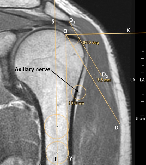
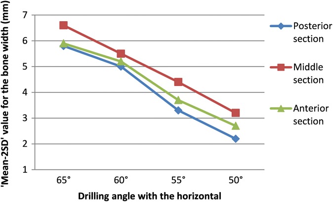
Methods: The drilling of a straight tunnel was simulated on 30 magnetic resonance imaging (MRI) scans in the oblique coronal plane by drawing a straight line that passed at a "safe distance" of 5 mm from the axillary nerve and emerging at the medial border of the insertion of the rotator cuff on the greater tuberosity. The angle made by this line with the horizontal axis of the humerus was measured on 3 MRI sections: anterior (passing just posterior to the lateral lip of the bicipital groove), middle (at the most lateral point of the proximal humerus), and posterior (an equal number of cuts away from the middle section as between anterior and middle). The thickness of the overlying bone roof was measured for this line as well as for simulation lines drawn at 50°, 55°, 60°, and 65° with the horizontal axis. A "safe limit," defined as the mean - 2SD, was also calculated.
Results: The axillary nerve was found to be safe, with a safety margin of 5 mm, at drill angles of less than 61.1° and 60.3° in the posterior and middle sections, respectively. The safe limit value for thickness of the overlying bone roof for the tunnel drilled at 60° was 5.0 mm in the posterior section (mean, 8.2 ± 0.3 mm) and 5.5 mm in the middle section (mean, 8.1 ± 0.2 mm). In the anterior section, the minimum safe angle was 57.7°, and the mean thickness of the bone roof for the 55° angle was 6.3 ± 0.2 mm (safe limit, 3.7 mm).
Conclusion: Straight bone tunnels in ATORCR surgery should be drilled at an angle of 60° to the horizontal axis of the humerus or 30° to the humeral shaft to ensure the safety of the axillary nerve while at the same time ensuring adequate thickness of the overlying bone roof. The anterior tunnel close to the bicipital groove should be drilled cautiously at 55° to the horizontal axis or 35° to the humeral shaft.
Clinical relevance: The findings of the present study will help the surgeon choose the best angle for drilling tunnels during ATORCR surgery to avoid axillary nerve injuries as well as suture cut-through without the need for any proprietary device.
Keywords: arthroscopic transosseous; axillary nerve; rotator cuff.
Conflict of interest statement
One or more of the authors has declared the following potential conflict of interest or source of funding: H.M. is the founder of and chief radiologist at Mahajan Imaging. AOSSM checks author disclosures against the Open Payments Database (OPD). AOSSM has not conducted an independent investigation on the OPD and disclaims any liability or responsibility relating thereto.
Figures


Similar articles
-
Is Arthroscopic Transosseous Rotator Cuff Repair Strength Dependent on the Tunnel Angle?Orthop J Sports Med. 2019 Jun 6;7(6):2325967119848667. doi: 10.1177/2325967119848667. eCollection 2019 Jun. Orthop J Sports Med. 2019. PMID: 31218236 Free PMC article.
-
Arthroscopic transosseous rotator cuff repair: how to avoid damaging the axillary nerve-a cadaveric study.Arch Orthop Trauma Surg. 2020 Nov;140(11):1767-1774. doi: 10.1007/s00402-020-03528-x. Epub 2020 Jul 25. Arch Orthop Trauma Surg. 2020. PMID: 32712820
-
Characterizing bone tunnel placement in medial ulnar collateral ligament reconstruction using patient-specific 3-dimensional computed tomography modeling.Am J Sports Med. 2013 Apr;41(4):894-902. doi: 10.1177/0363546513477377. Epub 2013 Feb 25. Am J Sports Med. 2013. PMID: 23439107
-
Medial portal drilling: effects on the femoral tunnel aperture morphology during anterior cruciate ligament reconstruction.J Bone Joint Surg Am. 2011 Nov 16;93(22):2063-71. doi: 10.2106/JBJS.J.01705. J Bone Joint Surg Am. 2011. PMID: 22262377 Review.
-
Arthroscopically assisted rotator cuff repair.Arthroscopy. 2004 Jul;20(6):620-6. doi: 10.1016/j.arthro.2004.04.058. Arthroscopy. 2004. PMID: 15241314 Review.
Cited by
-
Innovative boxing training program outperforms the traditional scapular stabilization training program in post-stroke patients.Sci Rep. 2024 Sep 9;14(1):21001. doi: 10.1038/s41598-024-71331-4. Sci Rep. 2024. PMID: 39251643 Free PMC article. Clinical Trial.
References
-
- Ahmad CS, Stewart AM, Izquierdo R, Bigliani LU. Tendon-bone interface motion in transosseous suture and suture anchor rotator cuff repair techniques. Am J Sports Med. 2005;33(11):1667–1671. - PubMed
-
- Baudi P, RasiaDani E, Campochiaro G, Rebuzzi M, Serafini F, Catani F. The rotator cuff tear repair with a new arthroscopic transosseous system: the Sharc-FT(®). Musculoskelet Surg. 2013;97(suppl 1):57–61. - PubMed
-
- Black EM, Austin LS, Narzikul A, Seidl AJ, Martens K, Lazarus MD. Comparison of implant cost and surgical time in arthroscopic transosseous and transosseous equivalent rotator cuff repair. J Shoulder Elbow Surg. 2016;25(9):1449–1456. - PubMed
-
- Burkhart SS, Johnson TC, Wirth MA, Athanasiou KA. Cyclic loading of transosseous rotator cuff repairs: tension overload as a possible cause of failure. Arthroscopy. 1997;13(2):172–176. - PubMed
LinkOut - more resources
Full Text Sources
