. 2018 Feb 28;28(9):1705291.
doi: 10.1002/adfm.201705291. Epub 2017 Dec 19.

Integration of stiff graphene and tough silk for the design and fabrication of versatile electronic materials

Affiliations

Integration of stiff graphene and tough silk for the design and fabrication of versatile electronic materials

Shengjie Ling et al. Adv Funct Mater. .

Abstract

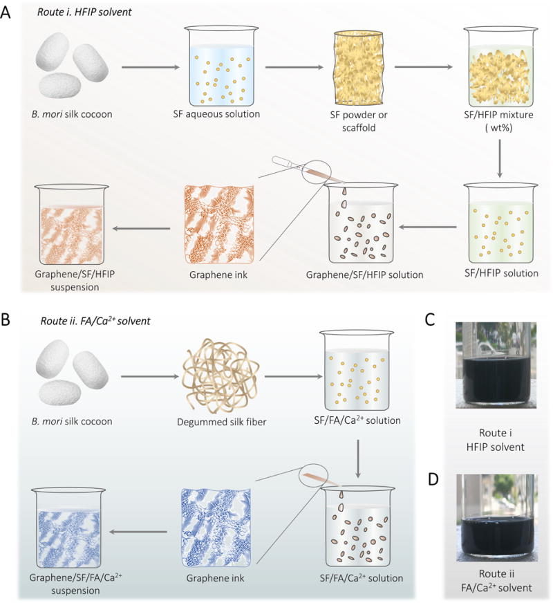
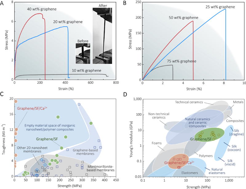
The production of structural and functional materials with enhanced mechanical properties through the integration of soft and hard components is a common approach to Nature's materials design. However, directly mimicking these optimized design routes in the lab for practical applications remains challenging. For example, graphene and silk are two materials with complementary mechanical properties that feature ultrahigh stiffness and toughness, respectively. Yet no simple and controllable approach has been developed to homogeneously integrate these two components into functional composites, mainly due to the hydrophobicity and chemical inertness of the graphene. In this study, well-dispersed and highly stable graphene/silk fibroin (SF) suspension systems were developed, which are suitable for processing to fabricate polymorphic materials, such as films, fibers, and coatings. The obtained graphene/SF nanocomposites maintain the electronic advantages of graphene, and they also allow tailorable mechanical performance to form including ultrahigh stretchable (with a strain to failure to 611±85%), or high strength (339 MPa) and high stiffness (7.4 GPa) material systems. More remarkably, the electrical resistances of these graphene/SF materials are sensitive to material deformation, body movement, as well as humidity and chemical environmental changes. These unique features promise their utility as wearable sensors, smart textiles, intelligent skins, and human-machine interfaces.

Keywords: Graphene; electronic materials; processing; silk.


Figures

Figure 1
Figure 1. The pathways to fabricate the well-dispersed graphene/SF/HFIP and graphene/SF/FA/Ca2+ suspensions
A, the route to produce graphene/SF/HFIP suspension. B, the process to produce graphene/SF/FA/Ca2+ suspension. C and D, photographs of the graphene/SF/HFIP (C) and graphene/SF/FA/Ca2 suspension (D) after incubation at room temperature for 7 days.
Figure 2
Figure 2. The versatile processability of graphene/SF/HFIP and graphene/SF/FA/Ca2+ suspensions
A-D, graphene/SF films produced from 10 wt% 75:25 graphene/SF/HFIP suspension. A, schematic diagram of solution casting method to make graphene/SF films. B-D, photographs of graphene/SF films. The graphene/SF films are flexible and conductive and can be folded or cut into arbitrary geometries. E-G, graphene/SF fibers spun from 10 wt% 50:50 graphene/SF/HFIP suspension. E, schematic of the wet-spinning method to generate graphene/SF fibers. F and G, photographs of the wet-spinning process (F) and the resultant fibers (G and insert image in F) obtained from graphene/SF/HFIP suspensions. The graphene/SF suspension solidified immediately once extruded into 70% v/v aqueous ethanol solution and the graphene/SF fibers were stable and strong. H-K, graphene/SF coating produced from 10 wt% 50:50 graphene/SF/FA/Ca2+ suspension. H, schematic of direct writing to make graphene/SF/Ca2+ coatings. I-K, photographs of graphene/SF coating generated by direct writing using a Chinese writing brush. The solidified coating layer bonded intensively with the polypropylene substrate and can withstand hundreds of rounds of tear tests using a commercial adhesive tape (J). The tear test did not destroy the conductive graphene/SF coating (K). Moreover, no resistance change was observed.
Figure 3
Figure 3. SEM images of graphene/SF/HFIP and graphene/SF/FA/Ca2+ materials
A, the cross-sectional SEM image of the graphene/SF film. B, surface SEM image of the graphene/SF film. The image reveals that SF was assembled into silk nanofibrils on the surface of the graphene. C, cross-sectional SEM image of the graphene/SF fiber. D, high-resolution SEM image of the cross-section of the graphene/SF fibers, indicating the porous structure of the fiber. E, cross-sectional SEM image of graphene/SF/Ca2+ coating. The top layer is the graphene/SF/ Ca2+ coating; the bottom layer is the polypropylene plate. F, high-resolution SEM image of the interface between of graphene/SF/Ca2+ coating and polypropylene plate.
Figure 4
Figure 4. Mechanical properties of graphene/SF and graphene/SF/ Ca2+ films
A, typical stress-strain curves of graphene/SF/Ca2+ films produced from 10 wt% graphene/SF/FA/Ca2+ suspensions with different weight percentages of graphene. The insert images are the photographs of the graphene/SF/Ca2+ spline with 20 wt% graphene before and after stretching. The spline was still stable with the strain around 300%. B, typical stress-strain curves of graphene/SF films produced from 10 wt% graphene/SF/HFIP suspensions with different weight percentages of graphene. C, comparison of the strength and toughness of graphene/SF and graphene/SF/Ca2+ materials with other mechanical advantageous polymer nanocomposites. The related data was extracted from refs [4] and [38]. D, comparison of the strength and stiffness (Young’s modulus) of graphene/SF and graphene/SF/Ca2+ materials with other natural and synthetic materials. Ashby plot of natural and synthetic materials are adapted from ref [39].
Figure 5
Figure 5. Graphene/SF and graphene/SF/ Ca2+ electronics
A and B, photographs of graphene/SF/Ca2+ spline with dimensions of 2 mm × 2 cm × 200 μm before (A) and after (B) tensile stretching, indicating resistance changes before and after spline stretching. C, strain-dependence of relative resistance changes for graphene/SF/Ca2+ nanocomposites. The insert plot is the dependence of the gauge factor of graphene/SF/Ca2+ nanocomposites on the strain. Open circles denote experimental data. The solid line represents the values calculated from the equation of GF=(ΔR/R0)/ε. D, the relative resistance changes for graphene/SF/Ca2+ nanocomposites during balloon deformation. The graphene/SF/Ca2+ spline adhered to the balloon surface. The insert photographs show the three states during balloon deformation, which correspond to the three points in time-relative resistance change plot. E, the relative resistance changes for graphene/SF/Ca2+ nanocomposites during finger movement. The relative resistance change follows finger movement. F and G, resistance responses of graphene/SF/Ca2+ nanocomposites for finger-touching (F) and breathing (G). H, resistance response of graphene/SF nanocomposites for aqueous ethanol solution with different ethanol and water volume ratios. The insert scheme shows the experimental setup used for measurement.

References

    1. Chen H, Müller MB, Gilmore KJ, Wallace GG, Li D. Adv Mater. 2008;20:3557.
    1. Novoselov KS, Falko VI, Colombo L, Gellert PR, Schwab MG, Kim K. Nature. 2012;490:192. - PubMed
    1. Potts JR, Dreyer DR, Bielawski CW, Ruoff RS. Polymer. 2011;52:5.
    1. Zhang Y, Gong S, Zhang Q, Ming P, Wan S, Peng J, Jiang L, Cheng Q. Chem Soc Rev. 2016;45:2378. - PubMed
    1. Ling S, Li C, Adamcik J, Wang S, Shao Z, Chen X, Mezzenga R. ACS Macro Lett. 2014;3:146. - PubMed

LinkOut - more resources