. 2018 Dec 18;115(51):12950-12955.
doi: 10.1073/pnas.1811823115. Epub 2018 Dec 4.

Multiresponsive polymeric microstructures with encoded predetermined and self-regulated deformability

Affiliations

Multiresponsive polymeric microstructures with encoded predetermined and self-regulated deformability

Yuxing Yao et al. Proc Natl Acad Sci U S A. .

Abstract

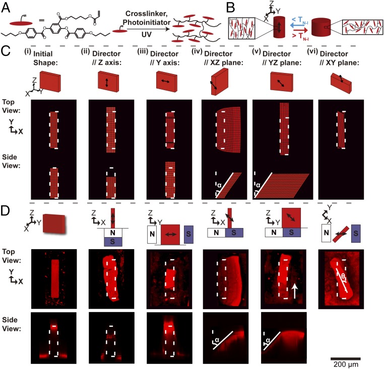
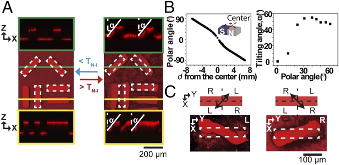
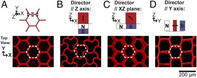
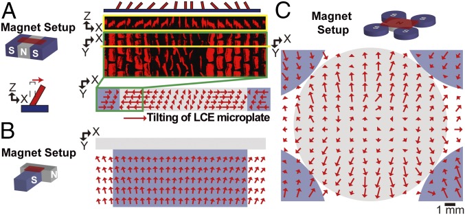
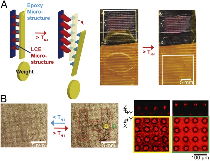
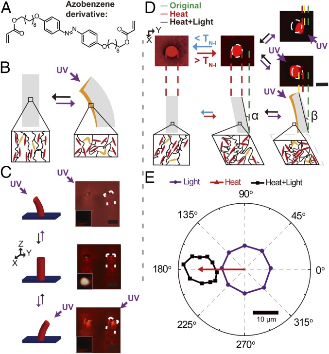
Dynamic functions of biological organisms often rely on arrays of actively deformable microstructures undergoing a nearly unlimited repertoire of predetermined and self-regulated reconfigurations and motions, most of which are difficult or not yet possible to achieve in synthetic systems. Here, we introduce stimuli-responsive microstructures based on liquid-crystalline elastomers (LCEs) that display a broad range of hierarchical, even mechanically unfavored deformation behaviors. By polymerizing molded prepolymer in patterned magnetic fields, we encode any desired uniform mesogen orientation into the resulting LCE microstructures, which is then read out upon heating above the nematic-isotropic transition temperature (TN-I) as a specific prescribed deformation, such as twisting, in- and out-of-plane tilting, stretching, or contraction. By further introducing light-responsive moieties, we demonstrate unique multifunctionality of the LCEs capable of three actuation modes: self-regulated bending toward the light source at T < TN-I, magnetic-field-encoded predetermined deformation at T > TN-I, and direction-dependent self-regulated motion toward the light at T > TN-I We develop approaches to create patterned arrays of microstructures with encoded multiple area-specific deformation modes and show their functions in responsive release of cargo, image concealment, and light-controlled reflectivity. We foresee that this platform can be widely applied in switchable adhesion, information encryption, autonomous antennae, energy harvesting, soft robotics, and smart buildings.

Keywords: actuators; autonomous materials multifunctionality; liquid-crystal elastomers.


Conflict of interest statement

The authors declare no conflict of interest.

Figures

Fig. 1.
Fig. 1.
Thermal-responsive LCE microplates with different internal molecular configurations. (A) Molecular structure of reactive LC monomer 4″-acryloyloxybutyl 2,5-di(4′-butyloxybenzoyloxy) benzoate and the polymerization process to form a side-on LCE. (B) Schematic illustration of the LCE micropillar that undergoes contraction during the N–I transition when the director is oriented along the structure—the case corresponding to 3D-printed or stretched microstructures. (C) Finite-element simulation results, showing the initial shape (i) and the types of deformation that will originate from the director orientation along the z axis (ii), along the y axis (note the contraction of the top surface in the y direction; iii), in the x–z plane (iv), in the y–z plane (v), and in the x–y plane (vi). White dashed outlines indicate the original shape of the microplate. (D, Top) Schematics showing the relative orientation and position of the plates (shown in red) in designed, 3D magnetic fields that give rise to the director orientations computed in C, iivi, respectively. Double-headed black arrows represent the director. (D, Bottom) Fluorescence confocal micrographs of the thermal-responsive deformation of the corresponding synthesized LCE microplates. White dashed outlines indicate the original shape of the LCE microplate. In D, v, the white arrow denotes the vector from the edge of the bottom surface to that of the top surface of the microplate, which has been shifted in the y direction. (C and D) The axes indicate the different planes of projection. α represents the tilting angle and θ illustrates the twisting angle.
Fig. 2.
Fig. 2.
Control over the deformation of 3D LCE microstructures. (A) Fluorescence confocal micrographs showing the tilting behavior of LCE microplates facing different directions in the magnetic field. Yellow and green panels show the reconstructed side views of the microplates at the marked regions. The tilt angle and direction are the same, irrespective of the orientation of the plates in a magnetic field. (B) Dependence of the tilting angle of a microplate on the polar angle of the LC director relative to the x–y plane. B, Left shows the COMSOL Multiphysics-calculated magnetic field that controls the polar angle of the LC director in the microstructures positioned at a distance d from the center. The continuously varying magnetic field and the associated changes in the LC director as a function of d result from the assembly of two block magnets with north (N) and south (S) poles pointing upward, respectively (only the top half of each magnet is shown). We define the center as the line where the magnets’ N and S poles meet, shown as the red dashed line in Inset. Zero polar angle corresponds to the microstructures positioned at the center, where the orientation of the director is parallel to the x–y plane. B, Right illustrates the experimentally measured tilting angle α of a microplate as a function of the polar angle of the LC director. (C) Control over the twist handedness of microplates by tuning the in-plane LC director. (C, Top) Schematic illustration of the in-plane LC director. (C, Bottom) The corresponding fluorescence confocal micrographs of twisted microplates. When the director is rotated clockwise from the x axis, i.e., oriented in the region marked “L” in the schematic, the microplate adopts a left-handed twist, as shown in the corresponding micrograph (Bottom Left). When the director is rotated counterclockwise from the x axis, i.e., oriented in the region marked “R” in the schematic, the microplate adopts a right-handed twist, as shown in the corresponding micrograph (Bottom Right).
Fig. 3.
Fig. 3.
Deformations of a honeycomb structure with various internal mesogenic configurations. (A) The schematic illustration and confocal fluorescence image of the original structure. (BD) Schematics (Top) and confocal fluorescence micrographs (Bottom) showing the deformed states of the honeycomb structure with the designed mesogenic orientation. The relative position of the black dashed wall in the magnetic field is shown at Top. All dashed white lines indicate the structure before deformation. The black double-headed arrows represent the LC director.
Fig. 4.
Fig. 4.
Fabrication of arrays of LCE microstructures. (AC) Two-dimensional spatial distribution of deformation angles of LCE microplate arrays polymerized in the presence of magnetic fields with (A) twofold, (B) T-shape, or (C) fourfold symmetry. In the schematics of the magnet setup, red blocks represent the position of the LCE microstructure array, and gray and blue blocks show the relative positions of N and S poles of the magnets, respectively. A, Right shows (Top to Bottom) a schematic illustration of the deformed array, the corresponding side- and top-view fluorescent confocal micrographs, and a representation of the deformations experienced by each member of the array. Each of the red arrows in A and B denotes the vector connecting the centers of the top surface of an LCE microplate in its undeformed and deformed states at the corresponding position (shown in A, Inset), thus indicating the direction and magnitude of tilting of the LCE microplates; in C, the arrows represent the average deformation of eight neighboring microplates (see SI Appendix, Fig. S10 for original fluorescence confocal micrographs). The gray and purple background denotes the N and S of the magnetic field, respectively.
Fig. 5.
Fig. 5.
Potential applications of arrays of LCE microstructures. (A) Schematic (Left) and experimental realization (Right) of a dynamic adhesion system based on cooperative movements of LCE microplates. The white boxes in the photographs indicate the position of the microstructured epoxy cargo (see Movie S4 and SI Appendix for more details). (B) An information storage system consisting of a stepwise write-in polymerization and a thermally induced readout. (B, Left) The optical appearance of the microstructure array in the undeformed and deformed states. The region H outside the red boundary was polymerized in the first step, using a mask without a magnetic field; the region inside H was polymerized in the second step upon the removal of the mask in the presence of a magnetic field. (B, Right) Confocal fluorescence micrographs of the yellow and green regions of the H pattern, showing different deformation modes of the structures polymerized in the first and second steps. Confocal fluorescence micrographs show different deformation behaviors in the regions polymerized at each step.
Fig. 6.
Fig. 6.
Light-responsive LCE microactuators. (A) Molecular structure of the azobenzene dopant. (B) Schematic illustration of the light-responsive LCE microstructure deformation. (C) Schematics (Left) and corresponding optical micrographs (Right) showing self-regulation of LCE micropillars toward the position of the light source. Insets show the optical reflection of the silver-coated LCE micropillars (see Movie S7 and SI Appendix for more details). Purple arrows represent the direction of the incident UV light. White dashed outlines show the position of the micropillar. (D) Fluorescence confocal micrographs (Top) and the corresponding schematic illustrations (Bottom) of a dual-responsive LCE micropillar. White dashed outlines denote the tip position of the micropillar upon heating above its TN–I. Green, red, and yellow vertical dashed lines show the edge position of the micropillar tip in the original state, heated above TN–I, and exposed to both heating and UV light, respectively. α and β denote the heat-responsive tilting angle and heat–light dual-responsive bending angle of the micropillar. Depending on the direction of the light-exposed wall, β > α when light is shone from the direction of the heat-induced tilt (Bottom Right confocal micrograph), and β < α when shone from the opposite side (Top Right confocal micrograph). (E) Quantitative characterization of the tip movements of a dual-responsive LCE micropillar subjected to heat, light, and a combination of heat and light.

References

    1. Vukusic P, Sambles JR, Lawrence CR, Wootton RJ. Structural colour. Now you see it–Now you don’t. Nature. 2001;410:36. - PubMed
    1. Xia F, Jiang L. Bio-inspired, smart, multiscale interfacial materials. Adv Mater. 2008;20:2842–2858.
    1. Autumn K, et al. Adhesive force of a single gecko foot-hair. Nature. 2000;405:681–685. - PubMed
    1. Tian Y, et al. Adhesion and friction in gecko toe attachment and detachment. Proc Natl Acad Sci USA. 2006;103:19320–19325. - PMC - PubMed
    1. Erb RM, Sander JS, Grisch R, Studart AR. Self-shaping composites with programmable bioinspired microstructures. Nat Commun. 2013;4:1712. - PubMed

Publication types

LinkOut - more resources