. 2018 Nov 20:12:816.
doi: 10.3389/fnins.2018.00816. eCollection 2018.

sPyNNaker: A Software Package for Running PyNN Simulations on SpiNNaker

Affiliations

sPyNNaker: A Software Package for Running PyNN Simulations on SpiNNaker

Oliver Rhodes et al. Front Neurosci. .

Abstract

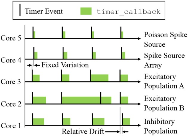
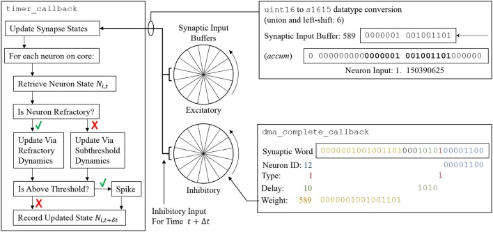
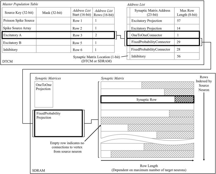
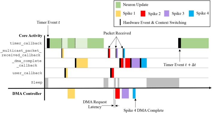
This work presents sPyNNaker 4.0.0, the latest version of the software package for simulating PyNN-defined spiking neural networks (SNNs) on the SpiNNaker neuromorphic platform. Operations underpinning realtime SNN execution are presented, including an event-based operating system facilitating efficient time-driven neuron state updates and pipelined event-driven spike processing. Preprocessing, realtime execution, and neuron/synapse model implementations are discussed, all in the context of a simple example SNN. Simulation results are demonstrated, together with performance profiling providing insights into how software interacts with the underlying hardware to achieve realtime execution. System performance is shown to be within a factor of 2 of the original design target of 10,000 synaptic events per millisecond, however SNN topology is shown to influence performance considerably. A cost model is therefore developed characterizing the effect of network connectivity and SNN partitioning. This model enables users to estimate SNN simulation performance, allows the SpiNNaker team to make predictions on the impact of performance improvements, and helps demonstrate the continued potential of the SpiNNaker neuromorphic hardware.

Keywords: PyNN; SpiNNaker machine; neuromorphic; realtime; spiking neural network (SNN).


Figures

Figure 1
Figure 1
The SpiNNaker Chip, containing: 18 cores, each with local instruction and data memory; network on chip; and SDRAM controller providing access to 128MB of chip-level shared memory.
Figure 2
Figure 2
SpiNNaker software stacks. From top left anti-clockwise to top right: users create SNN models on host via the PyNN interface; the sPyNNaker Python software stack then translates the SNN model into a form suitable for a SpiNNaker machine, and loads the appropriate data to SpiNNaker memory via Ethernet; sPyNNaker applications, built on the SARK system management and SpiN1API event-driven processing libraries, use the loaded data to perform realtime simulation of neurons and synapses.
Figure 3
Figure 3
Network partitioning to fit machine resources. (A) Application graph generated from interpretation of PyNN script: circles represent PyNN populations, and arrows PyNN projections. (B) Machine graph partitioned into vertices and edges to suit machine resources: squares represent populations (or partitioned sub-populations) of neurons which fit on a single SpiNNaker core—hence the model described by the machine graph in (B) requires 5 SpiNNaker cores for execution.
Figure 4
Figure 4
SpiNNaker realtime OS. (A) SpiN1API multi-threaded event-based operating system: scheduler thread to queue callbacks; dispatcher thread to execute callbacks; and FIQ thread to service interrupts from high-priority (-1) events. (B) Events and associated callbacks for updating neuron state variables, and processing incoming packets representing spikes into synaptic input. Figures reproduced with permission from Sharp et al. (2011, 2012).
Figure 5
Figure 5
Time-driven updates by neuron cores simulating the network in Figure 3B: periodic timer events trigger callbacks advancing neuron states by Δt. Cores can be out of phase due to communication of the start signal, and relative drift can occur due to manufacturing variability between boards. Note that state update times vary with the level of additional spike processing within a simulation timestep, however cores which experience high levels of spike activity delaying the subsequent timer_callback can catch up during subsequent periods of lower spike activity (as shown by Core 2).
Figure 6
Figure 6
(Left) Update flow advancing state of neuron Ni by Δt. (Center) Circular synaptic input buffers accumulate scaled input at different locations based on synaptic delay (buffers are rotated one slot at the end of every timestep). (Right top) Synaptic input buffer values are converted to fixed-point format and scaled before adding to Ni. (Right bottom) Decoding of synaptic word into circular synaptic buffer input.
Figure 7
Figure 7
Data structures for processing incoming spikes: Master Population Table, Address List, and Synaptic Matrix; shown from the perspective of the core simulating the Excitatory A population in Figure 3B. The path in bold represents that taken when a packet is received by Excitatory A, originating from itself, and hence two projections must be processed.
Figure 9
Figure 9
Interaction of callbacks shown over the time period between two timer events. Four spike events are processed representing the scenarios: receiving a packet while processing a timer event; receiving a packet while the core is idling; and receiving a packet while the spike processing pipeline is active. Note that a lighter color shade indicates suspension of a callback, which is resumed on completion of higher priority tasks.
Figure 8
Figure 8
Synaptic row structure with breakdown of substructures for both static and plastic synapses.
Figure 10
Figure 10
Output spike trains from realtime execution of the random balanced network of Figure 3A, from the PyNN script of Code S1. Spikes from inhibitory neurons are shown in red, and excitatory neurons in blue. The excitatory population receives an additional stimulus at t = 1s.
Figure 11
Figure 11
Total number of synaptic events which can be processed between timer events: solid lines represent cost model predictions, while markers show measurements taken from sPyNNaker simulations. (A) Variation of total synaptic events with connection probability for a range of simulated neurons per core. (B) Variation of total synaptic events with neurons per core for a range of connection probabilities.
Figure 12
Figure 12
DTCM footprint for neuron application simulating the Excitatory A population in Figure 3B.

References

    1. Akopyan F., Sawada J., Cassidy A., Alvarez-Icaza R., Arthur J., Merolla P., et al. (2015). TrueNorth: design and tool flow of a 65 mW 1 million neuron programmable neurosynaptic chip. IEEE Trans. Comput. Aided Design Integr. Circ. Syst. 34, 1537–1557. 10.1109/TCAD.2015.2474396 - DOI
    1. Amunts K., Ebell C., Muller J., Telefont M., Knoll A., Lippert T. (2016). The human brain project: creating a European research infrastructure to decode the human brain. Neuron 92, 574–581. 10.1016/j.neuron.2016.10.046 - DOI - PubMed
    1. ARM (2004). ARM968E-S Tech Reference Manual.
    1. Benjamin B. V., Gao P., McQuinn E., Choudhary S., Chandrasekaran A. R., Bussat J. M., et al. (2014). Neurogrid: a mixed-analog-digital multichip system for large-scale neural simulations. Proc. IEEE 102, 699–716. 10.1109/JPROC.2014.2313565 - DOI
    1. Brown A. D., Furber S. B., Reeve J. S., Garside J. D., Dugan K. J., Plana L. A., et al. (2015). SpiNNaker - Programming model. IEEE Trans. Comput. 64, 1769–1782. 10.1109/TC.2014.2329686 - DOI