. 2018 Dec 7;4(12):eaau6419.
doi: 10.1126/sciadv.aau6419. eCollection 2018 Dec.

Field responsive mechanical metamaterials

Affiliations

Field responsive mechanical metamaterials

Julie A Jackson et al. Sci Adv. .

Abstract

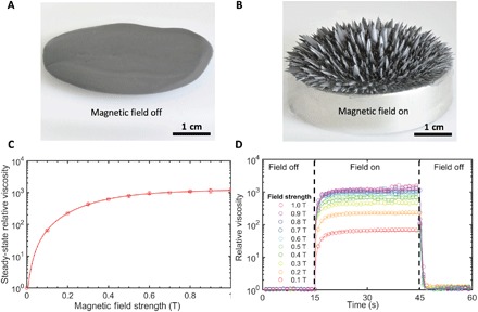
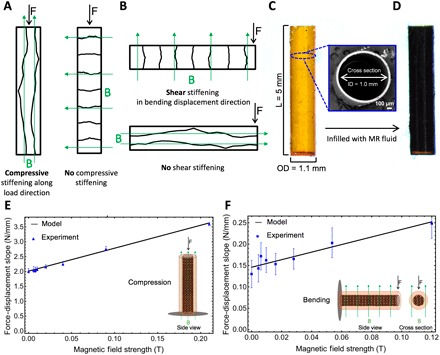
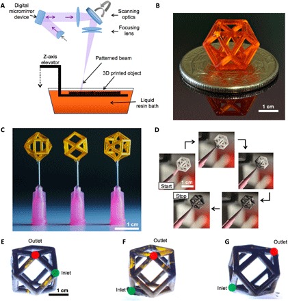
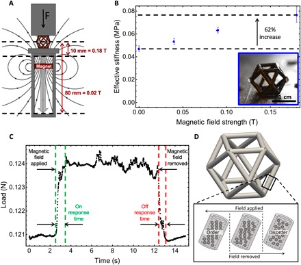
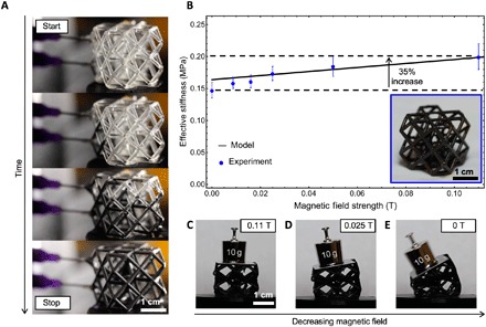
Typically, mechanical metamaterial properties are programmed and set when the architecture is designed and constructed, and do not change in response to shifting environmental conditions or application requirements. We present a new class of architected materials called field responsive mechanical metamaterials (FRMMs) that exhibit dynamic control and on-the-fly tunability enabled by careful design and selection of both material composition and architecture. To demonstrate the FRMM concept, we print complex structures composed of polymeric tubes infilled with magnetorheological fluid suspensions. Modulating remotely applied magnetic fields results in rapid, reversible, and sizable changes of the effective stiffness of our metamaterial motifs.


Figures

Fig. 1
Fig. 1. Structure onset and rheological tests of MR fluids in response to applied magnetic field.
(A) Optical image of the MR fluid forming a liquid pool on a planar substrate in the absence of a magnetic field. (B) Optical image of the MR fluid forming ordered, blade-like columns in the presence of a magnetic field. (C) Rheological plot of the MR fluid’s relative steady-state viscosity, which increases with increasing applied magnetic field strength. The field off steady-state viscosity is 140 cP. (D) Rheological plot demonstrating the response time of the MR fluid at various magnetic field strengths.
Fig. 2
Fig. 2. Single strut characterization.
(A and B) Schematic illustrations of how the magnetic field application direction affects the stiffening of a strut. (A) In the axial case, a magnetic field applied transverse to the strut will produce no increase in axial stiffness, regardless of field strength applied. (B) In the bending case, a magnetic field applied perpendicular to the displacement will have no effect on bending stiffness, regardless of the field strength applied. (C) Side view optical image of the hollow polymer strut before infilling with MR fluid. Inset is a scanning electron microscopy micrograph of the hollow polymer strut cross section. (D) Side view optical image after infilling with MR fluid. The strut dimensions are 1.0-mm inner diameter (ID), 1.1-mm outer diameter (OD), 50-μm wall thickness, and 5-mm length (L). (E and F) Force-displacement slope versus magnetic field strength plots. (E) Uniaxial compression showing experimental results and model calibration. Inset is a schematic illustration of the experimental setup from the side view. (F) Cantilevered bending showing experimental results and model calibration. Inset is a schematic illustration of the experimental setup from the side and cross-sectional views.
Fig. 3
Fig. 3. 3D printing and MR fluid infilling of unit cells.
(A) Schematic illustration of the LAPμSL 3D printing process used to build struts, unit cells, and lattices. (B) Optical image of a resin-filled polymer cuboctahedron unit cell. (C) Optical image of drained (hollow) unit cells affixed with a dissolvable wax to syringe nozzles for infilling. (D) Optical images from a time-lapse recording of the MR fluid infilling process. (E to G) Optical image of the unit cell with inlet (green) and outlet (red) ports separated by various strut lengths. (E) Ports separated by one strut. (F) Ports separated by two struts. (G) Ports separated by three struts with the highest degree of infilling.
Fig. 4
Fig. 4. Magnetomechanical characterization of cuboctahedron unit cells.
(A) Schematic illustration of the experimental setup for mechanical testing of MR fluid–filled samples with magnetic field strength controlled by translating a permanent magnet close to or away from the sample while measuring mechanical properties. (B) Plot of effective stiffness versus magnetic field strength for the cuboctahedron unit cell showing a 62% increase in stiffness from 0 to 0.18 T. Inset is an optical image of the MR fluid–filled unit cell. (C) Load versus time plot for one example of cycling a unit cell between field off (0.0 T) and field on (0.10 T) states to measure response times. (D) Schematic illustration of how the particles switch from ordered to disordered structures within the MR fluid–filled struts of the unit cells during field application or removal.
Fig. 5
Fig. 5. Infilling and magnetomechanical behavior of cuboctahedron lattices.
(A) Optical images showing a time lapse of the infilling process for a cuboctahedron lattice composed of a 2 by 2 by 2 unit cell arrangement. (B) Plot of the effective stiffness versus magnetic field strength for the cuboctahedron lattice showing a 35% increase in stiffness for 0 to 0.11 T. Inset is an optical image of the MR fluid–filled lattice. (C to E) Optical images of the MR fluid–filled lattice supporting a 10-g weight under various magnetic field strengths. (C) MR fluid–filled lattice supporting a static 10-g mass with a maximum magnetic field of 0.11 T applied. (D) Compression of the lattice as the applied field is reduced. (E) Bending of the lattice structure under the weight of the 10-g mass as the magnetic field is removed.

References

    1. L. J. Gibson, M. F. Ashby, Cellular Solids: Structure and Properties (Cambridge Univ. Press, 2001).
    1. M. Meyers, K. Chawla, Mechanical Behavior of Materials (Cambridge Univ. Press, ed. 2, 2009).
    1. Gibson L. J., Biomechanics of cellular solids. J. Biomech. 38, 377–399 (2005). - PubMed
    1. Wadley H. N. G., Cellular metals manufacturing. Adv. Eng. Mater. 4, 726–733 (2002).
    1. Lehmhus D., Vesenjak M., Schampheleire S. d., Fiedler T., From stochastic foam to designed structure: Balancing cost and performance of cellular metals. Materials 10, 922 (2017). - PMC - PubMed