

Design of an Artificial Neural Network Algorithm for a Low-Cost Insole Sensor to Estimate the Ground Reaction Force (GRF) and Calibrate the Center of Pressure (CoP)
- PMID: 30544652
- PMCID: PMC6308711
- DOI: 10.3390/s18124349
Design of an Artificial Neural Network Algorithm for a Low-Cost Insole Sensor to Estimate the Ground Reaction Force (GRF) and Calibrate the Center of Pressure (CoP)
Abstract
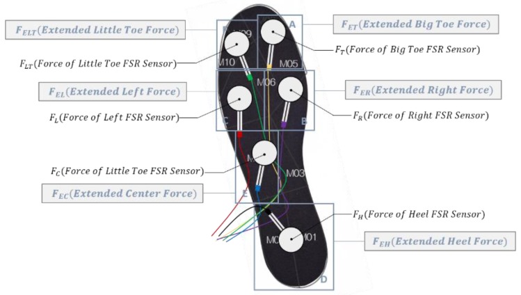
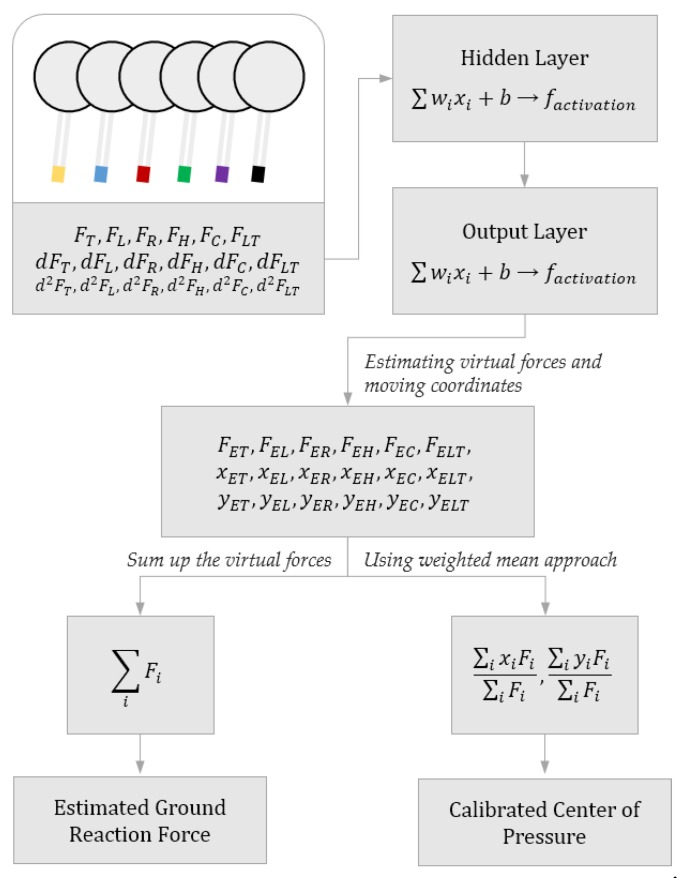
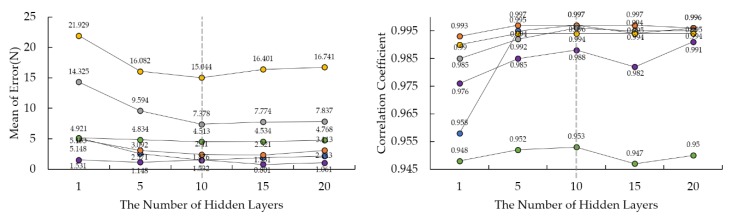
As an alternative to high-cost shoe insole pressure sensors that measure the insole pressure distribution and calculate the center of pressure (CoP), researchers developed a foot sensor with FSR sensors on the bottom of the insole. However, the calculations for the center of pressure and ground reaction force (GRF) were not sufficiently accurate because of the fundamental limitations, fixed coordinates and narrow sensing areas, which cannot cover the whole insole. To address these issues, in this paper, we describe an algorithm of virtual forces and corresponding coordinates with an artificial neural network (ANN) for low-cost flexible insole pressure measurement sensors. The proposed algorithm estimates the magnitude of the GRF and the location of the foot plantar CoP. To compose the algorithm, we divided the insole area into six areas and created six virtual forces and the corresponding coordinates. We used the ANN algorithm with the input of magnitudes of FSR sensors, 1st and 2nd derivatives of them to estimate the virtual forces and coordinates. Eight healthy males were selected for data acquisition. They performed an experiment composed of the following motions: standing with weight shifting, walking with 1 km/h and 2 km/h, squatting and getting up from a sitting position to a standing position. The ANN for estimating virtual forces and corresponding coordinates was fitted according to those data, converted to c script, and downloaded to a microcontroller for validation experiments in real time. The results showed an average RMSE the whole experiment of 31.154 N for GRF estimation and 8.07 mm for CoP calibration. The correlation coefficients of the algorithm were 0.94 for GRF, 0.92 and 0.76 for the X and Y coordinate respectively.
Keywords: artificial neural network (ANN); center of pressure (CoP); force sensing resistor (FSR); ground reaction force (GRF).
Conflict of interest statement
The authors declare no conflict of interest.
Figures
References
-
- Perry J., Davids J.R. Gait Analysis: Normal and Pathological Function. J. Pediatr. Orthop. 1992;12:815. doi: 10.1097/01241398-199211000-00023. - DOI
-
- Bouffard V., Nantel J., Therrien M., Vendittoli P.A., Lavigne M., Prince F. Center of Mass Compensation during Gait in Hip Arthroplasty Patients: Comparison between Large Diameter Head Total Hip Arthroplasty and Hip Resurfacing. Rehabil. Res. Pract. 2011;2001 doi: 10.1155/2011/586412. - DOI - PMC - PubMed
Grants and funding
LinkOut - more resources
Full Text Sources
Research Materials
