. 2018 Dec 13;9(1):5303.
doi: 10.1038/s41467-018-07721-w.

Closed-loop functional optogenetic stimulation

Affiliations

Closed-loop functional optogenetic stimulation

Shriya S Srinivasan et al. Nat Commun. .

Abstract

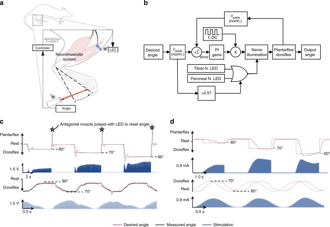
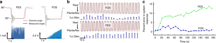
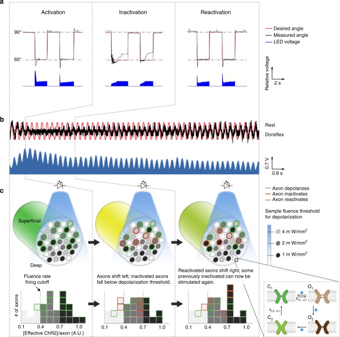
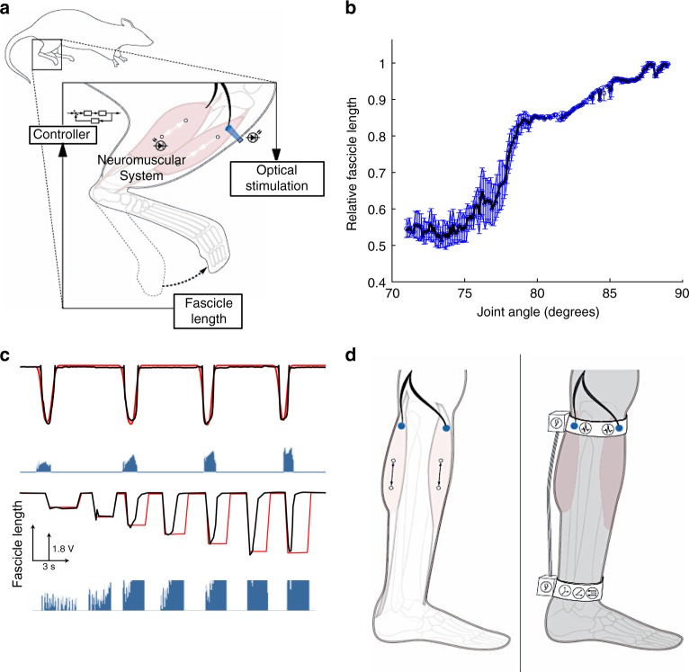
Optogenetics has been used to orchestrate temporal- and tissue-specific control of neural tissues and offers a wealth of unique advantages for neuromuscular control. Here, we establish a closed-loop functional optogenetic stimulation (CL-FOS) system to control ankle joint position in murine models. Using the measurement of either joint angle or fascicle length as a feedback signal, we compare the controllability of CL-FOS to closed-loop functional electrical stimulation (CL-FES) and demonstrate significantly greater accuracy, lower rise times and lower overshoot percentages. We demonstrate orderly recruitment of motor units and reduced fatigue when performing cyclical movements with CL-FOS compared with CL-FES. We develop and investigate a 3-phase, photo-kinetic model to elucidate the underlying mechanisms for temporal variations in optogenetically activated neuromusculature during closed-loop control experiments. Methods and insights from this study lay the groundwork for the development of closed-loop optogenetic neuromuscular stimulation therapies and devices for peripheral limb control.


Conflict of interest statement

The authors declare no competing interests.

Figures

Fig. 1
Fig. 1
Closed-loop optogenetic system. a Schematic of system design for CL-FOS. The peroneal or tibial nerve was optically stimulated using an LED, resulting in a contraction of the tibialis anterior or gastrocnemius muscle, yielding dorsiflexion or plantarflexion, respectively. Measurement of the footpad displacement was fed into the controller, which modulated the stimulation intensity to bring the limb to the desired angle. b Control diagram depicting pseudo-SITO (single input, two outputs) structure employed for CL-FOS control of the joint angle with PI gains where f: frequency, DC: duty cycle. c Representative trial of CL-FOS accuracy under PI control utilizing a virally transduced rat. Average SSRMSE was 3.01 ± 1.32% for square wave patterns and 1.16 ± 0.93% for sinusoidal patterns (n = 12). d Representative trial of CL-FES accuracy under PI control utilizing a virally transduced rat. Average SSRMSE was 6.31 ± 2.98% for square wave patterns and 11.18 ± 4.32% for sinusoidal patterns (n = 11)
Fig. 2
Fig. 2
Comparison of recruitment and fatigue between FOS and FES. a Comparison of electrical and optical stimulation for CL control. CL-FES uses a more constant stimulation profile as compared to the growing profile of CL-FOS, corresponding to its motor unit recruitment pattern. b System response (black) to cyclic CL square wave pattern (red) alternating between rest and plantar flexion (FOS: 1.25 ms PW, 40 Hz, Ti = 5E−6 s−1, Kp = 1E−2; FES: 100 µs PW, 40 Hz, Ti = 4E−4 s−1, Kp = 5E−3). Percent change in stimulation (blue) calculated by comparing the peak value during each cycle with the value during the first cycle. c Percent error in system response from desired angle for FES and FOS systems over the time course of stimulation. These representative data were drawn from trials performed in rats
Fig. 3
Fig. 3
Three-phase, photo-kinetic behavior of optogenetic system. a Representative behavior during each phase of the three-phase system response. This representative data are from trials performed in rats. Stimulation is sufficient to maintain the desired position in the activation and reactivation phases, but not the inactivation phase. b System response (black) to desired sinusoidal pattern (red) and stimulation delivered by the controller (blue) occurring in the 3 distinct phases of (1) activation, (2) inactivation, and (3) reactivation. This representative data are from a trial performed in a mouse. c Schematic depicting optogenetic stimulation of nerve in response to increasing illumination intensities as well as open and closed states modeled for ChR2. [Effective ChR2] is defined as [ChR2O1] + [ChR2O2] × (IO2/IO1). In this representative case, if appropriate dorsiflexion or plantar flexion requires the simultaneous activation of all 12 axons, then it will be achieved in the activation phase but not in the inactivation or reactivation phases. However, if only 9 of the initial 12 axons are required, then angle control will be achieved in the activation and reactivation phases, but not the inactivation phase
Fig. 4
Fig. 4
Direct fascicle sensing through sonomicrometry. a Schematic depicting closed-loop experimental paradigm using sonomicrometry crystals for fascicle state measurement. b Plot of points derived from a closed-loop run defining the fascicle length across the range of joint angles. The relationship between relative fascicle length and joint angle demonstrates passive and active contracting segments throughout range of dorsiflexion (90°–70°). These representative data were obtained from trials in virally transduced rats. c Closed-loop control of joint angle using sonomicrometry feedback regarding fascicle length demonstrating smooth sinusoidal movement (top: red—desired, black—actual) and dynamic range in end angle (bottom: red—desired, black—actual). This representative trial was performed in a transgenic mouse. d Schematic of the implementation of closed-loop optogenetic/sonomicrometry-driven systems; transdermal (left) and implantable (right)

Similar articles

Cited by

References

    1. Peckham PH, Creasey GH. Neural prostheses: clinical applications of functional electrical stimulation in spinal cord injury. Spinal Cord. 1992;30:96–101. doi: 10.1038/sc.1992.33. - DOI - PubMed
    1. da L. dos Santos. E, et al. Artificial motor control for electrically stimulated upper limbs of plegic or paretic people. Res. Biomed. Eng. 2016;32:199–211. doi: 10.1590/2446-4740.03415. - DOI
    1. Bailey SN, et al. Neurotherapeutic and neuroprosthetic effects of implanted functional electrical stimulation for ambulation after incomplete spinal cord injury. J. Rehabil. Res. Dev. 2010;47:7–16. doi: 10.1682/JRRD.2009.03.0034. - DOI - PubMed
    1. Peckham PH, Knutson JS. Functional electrical stimulation for neuromuscular applications. Annu. Rev. Biomed. Eng. 2005;7:327–360. doi: 10.1146/annurev.bioeng.6.040803.140103. - DOI - PubMed
    1. Llewellyn ME, Thompson KR, Deisseroth K, Delp SL. Orderly recruitment of motor units under optical control in vivo. Nat. Med. 2010;16:1161–1165. doi: 10.1038/nm.2228. - DOI - PMC - PubMed

Publication types