. 2018 Jul 27;33(14):2040-2051.
doi: 10.1557/jmr.2018.178. Epub 2018 Jun 18.

Structure-Property Relationships for 3D printed PEEK Intervertebral Lumbar Cages Produced using Fused Filament Fabrication

Affiliations

Structure-Property Relationships for 3D printed PEEK Intervertebral Lumbar Cages Produced using Fused Filament Fabrication

Cemile Basgul et al. J Mater Res. .

Abstract

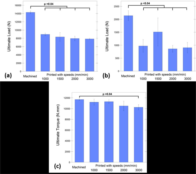
Recent advances in additive manufacturing technology now enable fused filament fabrication (FFF) of Polyetheretherketone (PEEK). A standardized lumbar fusion cage design was 3D printed with different speeds of the print head nozzle to investigate whether 3D printed PEEK cages exhibit sufficient material properties for lumbar fusion applications. It was observed that the compressive and shear strength of the 3D printed cages were 63-71% of the machined cages, whereas the torsion strength was 92%. Printing speed is an important printing parameter for 3D printed PEEK, which resulted in up to 20% porosity at the highest speed of 3000 mm/min, leading to reduced cage strength. Printing speeds below 1500 mm/min can be chosen as the optimal printing speed for this printer to reduce the printing time while maintaining strength. The crystallinity of printed PEEK did not differ significantly from as-machined PEEK cages from extruded rods, indicating that the processing provides similar microstructure.


Figures

FIG. 1
FIG. 1
The CAD drawing (a) shows the design parameters for the cage used in this study. A batch of six cages was created with support structures on the heated bed (b) and g-code was created after the addition of the brims around the cages (c) on the Simplify 3D software.
FIG. 2
FIG. 2
Machined cages (a-right) were manufactured from PEEK OPTIMA LT1 rod and FFF cages (a-left) were printed with the filament of PEEK OPTIMA LT1 and a customized PEEK printer (b).
FIG. 3
FIG. 3
Under compressive loading, slowest printed cages were able to provide 63% ultimate strength of the machined cages (a), under compressive-shear loading, the cohort printed with 1500 mm/min speed showed 71% ultimate load of the machined cages, however they were both significantly lower than machined cages (b). Under torsional loading, cohorts printed with 1000, 1500, and 2000 mm/min showed comparable (92% on average) ultimate moment with the machined cages and with no significant differences (c).
FIG. 4
FIG. 4
Porosity in cohorts. Increasing the printing speed increased the porosity of printed cages significantly (a). Mean porosity difference was 18% between the slowest printed (1000 mm/min) (c) and the fastest printed cohort (3000 mm/min) (d). Average pore sizes of printed cohorts were between 80-135 microns and there was not a significant correlation between printing speed and average pore size (b).
FIG. 5
FIG. 5
Although average pore size did not significantly increase by increasing the printing speed, porosity was observed in all FFF cages (e) printed with 1000 (a), 1500 (b), 2000 (c) and 3000 (d) mm/min speed. However, both average pore size and porosity percentage of machined cages were not detected from micro-CT 3D scans (f).
FIG. 6
FIG. 6
Partial fusion of the layers (a) and unfused layers (b) both observed in a surface (a). Additional porosity might be caused by external factors such as nozzle removal from the print surface (c).
FIG. 7
FIG. 7
Under compressive (a-b) and shear loading (c) conditions the cracks were aligned parallel with the layers. However, under the torsional loading condition, the crack initiated along the printed layers it continued perpendicular to the printed layers (d).
FIG. 8
FIG. 8
Crack and layer width were measured from printed cohorts after compression testing (a). Increasing the printing speed caused a greater layer width (b), however crack width was not significantly correlated with the print speed (c).

References

    1. Tack P, Victor J, Gemmel P, Annemans L. 3D-printing techniques in a medical setting: a systematic literature review. Biomed Eng Online. 2016;15(1):115. - PMC - PubMed
    1. Eltorai AE, Nguyen E, Daniels AH. Three-Dimensional Printing in Orthopedic Surgery. Orthopedics. 2015;38(11):684. - PubMed
    1. Gibbs DM, Vaezi M, Yang S, Oreffo RO. Hope versus hype: what can additive manufacturing realistically offer trauma and orthopedic surgery? Regen Med. 2014;9(4):535. - PubMed
    1. Martelli N, Serrano C, van den Brink H, Pineau J, Prognon P, Borget I, El Batti S. Advantages and disadvantages of 3-dimensional printing in surgery: A systematic review. Surgery. 2016;159(6):1485. - PubMed
    1. Provaggi E, Leong JJH, Kalaskar DM. Applications of 3D printing in the management of severe spinal conditions. Proc Inst Mech Eng H. 2017;231(6):471. - PubMed