Review
. 2019 Jan;31(1):e1804041.
doi: 10.1002/adma.201804041. Epub 2018 Nov 22.

Minimally Invasive and Regenerative Therapeutics

Affiliations
Review

Minimally Invasive and Regenerative Therapeutics

Nureddin Ashammakhi et al. Adv Mater. 2019 Jan.

Abstract

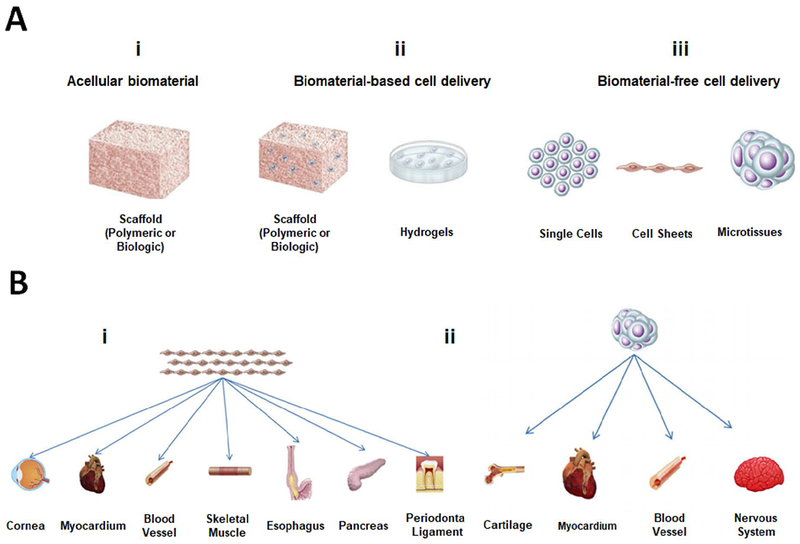
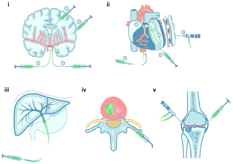
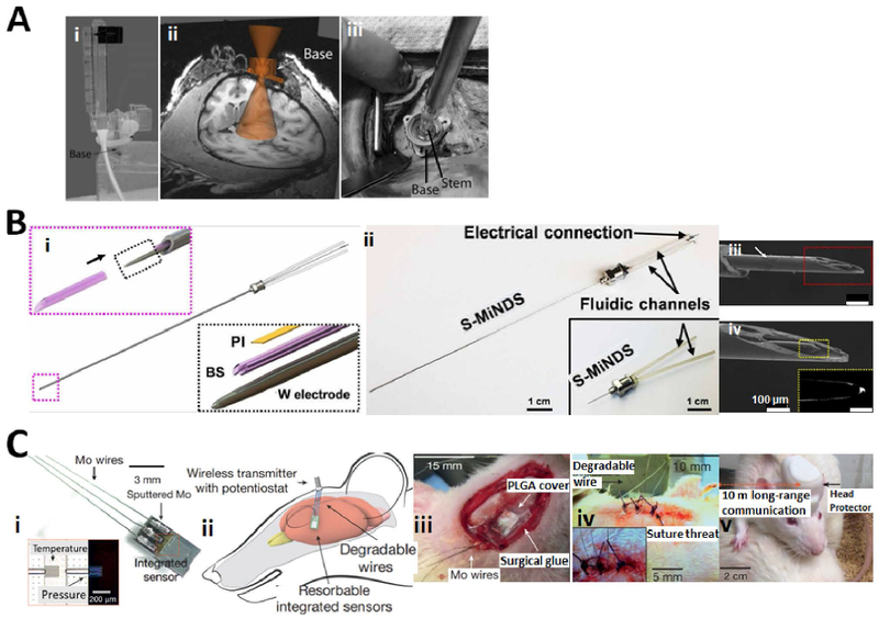
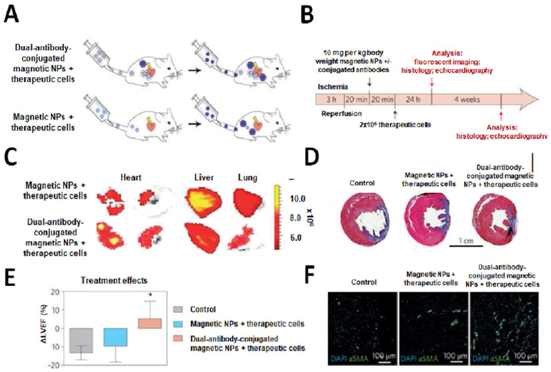
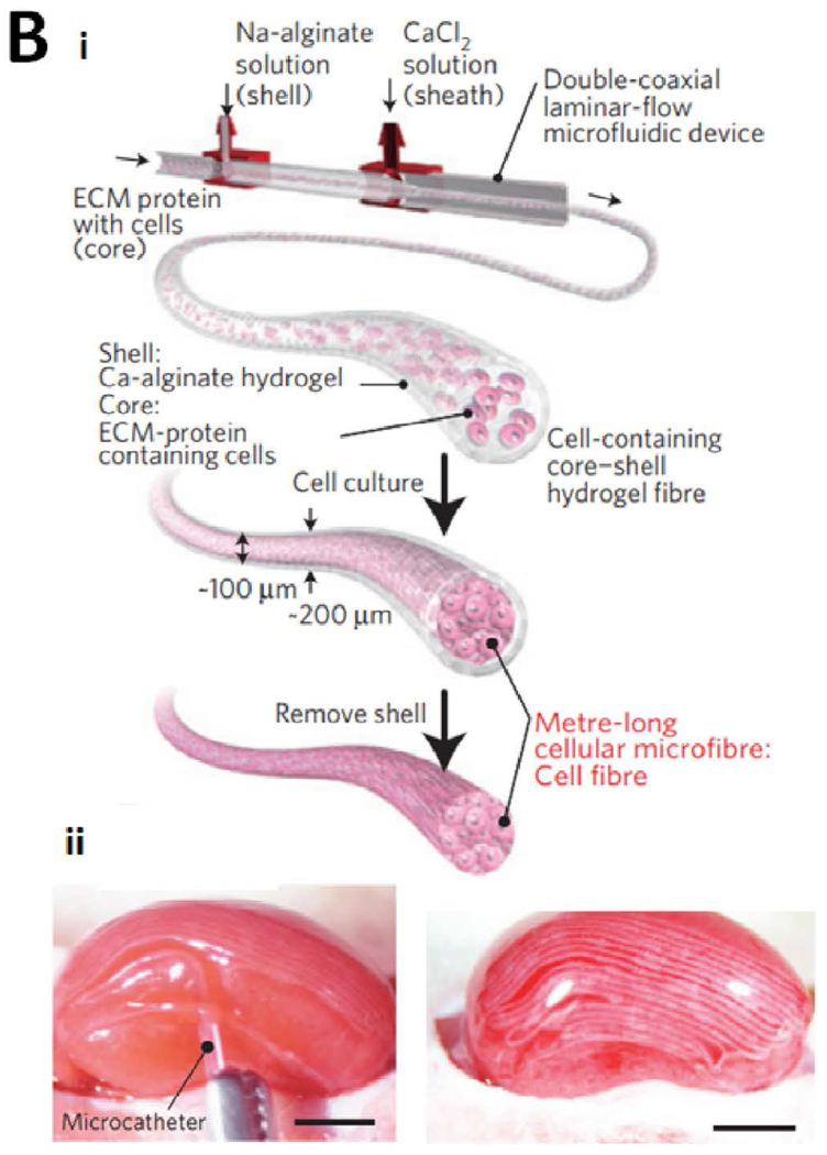
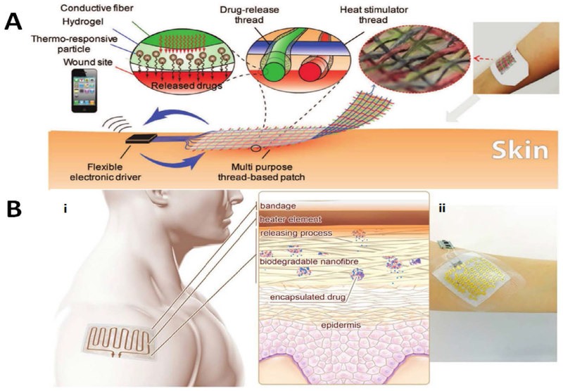
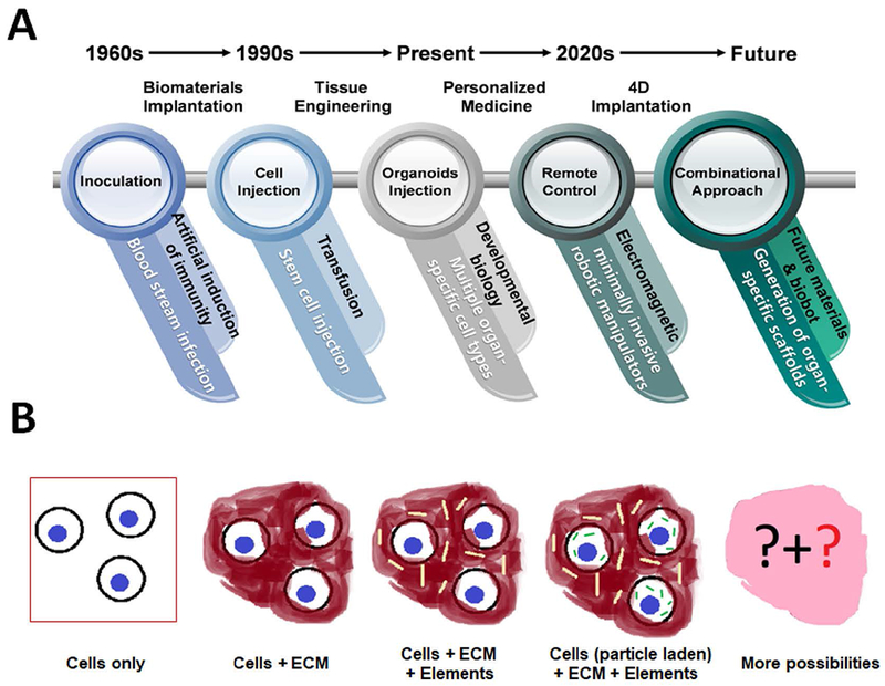
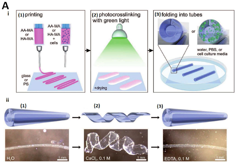
Advances in biomaterial synthesis and fabrication, stem cell biology, bioimaging, microsurgery procedures, and microscale technologies have made minimally invasive therapeutics a viable tool in regenerative medicine. Therapeutics, herein defined as cells, biomaterials, biomolecules, and their combinations, can be delivered in a minimally invasive way to regenerate different tissues in the body, such as bone, cartilage, pancreas, cardiac, skeletal muscle, liver, skin, and neural tissues. Sophisticated methods of tracking, sensing, and stimulation of therapeutics in vivo using nano-biomaterials and soft bioelectronic devices provide great opportunities to further develop minimally invasive and regenerative therapeutics (MIRET). In general, minimally invasive delivery methods offer high yield with low risk of complications and reduced costs compared to conventional delivery methods. Here, minimally invasive approaches for delivering regenerative therapeutics into the body are reviewed. The use of MIRET to treat different tissues and organs is described. Although some clinical trials have been performed using MIRET, it is hoped that such therapeutics find wider applications to treat patients. Finally, some future perspective and challenges for this emerging field are highlighted.

Keywords: biomaterials; biomolecules; delivery; minimally invasive; scaffolds; tissue regeneration.


Figures

Figure 1.
Figure 1.. Applications of minimally invasive therapeutics to regenerate different parts of the body.
(A) Different MIRET including (i) acellular biomaterials, (ii) biomaterial-based cell delivery, and (iii) biomaterial-free cell delivery. (B) Biomaterial-free cell delivery approaches to regenerate different parts of the body. A and B are reproduced with permission from [376].
Figure 2.
Figure 2.. Minimally invasive approaches to deliver regenerative therapeutics into the (i) brain, (ii) heart, (iii) liver, (iv) IVD, and (v) knee joint.
Minimally invasive and regenerative therapy can be achieved using direct injection, endoscope, or catheter. Redrawn and modified from [377].
Figure 3.
Figure 3.. Minimally invasive and remotely controllable delivery of drugs to the brain.
(A) (i) Photograph of the device base with remote introducer and guiding insert. (ii) Placement of the base on the skull was guided by a cone of projection using MRI. (iii) Surgical demonstration of device application on the primate’s skull using laser calibration rod inserted in the stem. Three self-tapping screws were used to secure the base in the place. Reproduced with permission from [46]. (B) (i) Main components of miniaturized drug delivery system (S-MiNDS) with enlarged components (tungsten (W) electrode and polyimide (PI) template) and borosilicate (BS) aligner tip that aligns with the key device components following arrow direction. (ii) S-MiNDS images with the fluidic channels and electrical connection. (iii, iv) Scanning electron microscopy (SEM) images of the tip of the device including magnified image of BS aligner tip in red rectangular and W electrode in the yellow rectangular. Reproduced with permission from [190]. (C) (i) Bioresorbable sensors integrated with dissolvable metal connects and biodegradable wires. Inset: optical micrograph of serpentine silicon nano-membrane of the sensing parts. Temperature sensor is not on the air cavity while the pressure sensor is on the edge of air cavity. (ii) Biodegradable sensors intracranially implanted in rat and connected to an external wireless data-transmission unit. (iii) Demonstration of an implanted bioresorbable sensor in the rat. A thin film of PLGA with 80-μm thickness and a dissolvable surgical glue were used to seal the craniectomy. (iv) A sutured mouse and (v) a freely moving mouse with implanted biosensor. Reproduced with permission from [362].
Figure 4.
Figure 4.. Dual-antibody-conjugated SMIONs for targeted cell delivery to the injured myocardium.
(A, B) Schematics and timeline of the delivery of NPs and cells with and without conjugated antibody. (C) Fluorescent imaging of rat’s organs 24 hrs after cell injection, showing the effect of incorporating antibodies in magnetic NPs on decreasing off-target cell distribution. Rats which received the dual-antibody-conjugated magnetic NPs have more targeted accumulation in their organs compared to those injected with regular magnetic NPs. (D) The whole heart section imaging (trichrome staining) four weeks after reperfusion showed a prominent depletion of scar size (blue) and significant increase in viable (red) tissues in animals, which received dual-antibody-conjugated SMIONs compared to control sample and regular magnetic NPs. (E) Echocardiography results four weeks after reperfusion confirmed that left ventricular ejection fraction in the targeted-NP group was significantly improved compared to the control and regular NPs groups. (F) Confocal microscopic images: NP-targeted cell therapies can greatly improve the angiogenesis compared to the control and regular NP groups. Blue denotes DAPI for cell nuclei and green represents alpha smooth muscle actin (α-SMA) for smooth muscle cells. Reproduced with permission from [378].
Figure 5.
Figure 5.. Shape-memory scaffolds for minimally invasive delivery of cardiac patches.
(A) An illustration demonstrating shape-memory scaffold for delivering cardiomyocytes to the epicardium using thoracoscopy. The cardiac patch is first loaded into the throacoscope. Then, upon releasing it recovered its shape and extended out to sit on the heart. (B) Photographs showing fluorescence images of live (green) and dead (red) neonatal rat cardiomyocytes on the patch before and after injection. Pictures were reproduced with permission from [2].
Figure 6.
Figure 6.. Different biomaterial designs to promote recovery after SCI.
Tubular scaffolds are beneficial for resection or full transection in injuries. Injuries can also be occupied with fibers or pores for cell growth. Hydrogels with drugs or cells can fill the defect area. Soft hydrogels can be intrathecally injected as MIRET.
Figure 7.
Figure 7.. Injectable cell-laden hydrogels in brain repair.
(A) Injectable self-healing hydrogels made of N-carboxyethyl chitosan (CEC) and oxidized sodium alginate (OSA) carrying NSCs for transplantation. The cell-laden hydrogels were cultured in DF-12 medium at 37 ºC. and then injected using needles into the lesion cavity. Reproduced with permission from [216]. (B) Electrospun scaffolds support induced neuronal cells (iNs) outgrowth and survival in vivo and ex vivo. (i, ii) The scaffolds seeded with the iNs were injected into the mouse striatum and onto the mouse pup brain slices. Compared to only green fluorescent protein-labelled iNs (iii), transplanted scaffold-supported iNs (iv) significantly enhanced the neurite length when injected onto the mouse brain slices ex vivo (n=8 brain slices for each transplantation mode). Reproduced with permission form [217].
Figure 8.
Figure 8.. Fabrication and implantation of microfibers for minimally invasive delivery of therapeutics.
(A) (i) Fiber fabrication using microfluidic system. The fibers were continuously extruded, gelated, and collected on the rotating spool. (ii) Schematic of silk-spinning by spiders. Proteins are produced by the silk gland, and in the spinning duct, protein solutions are solidified while spider’s valve controls the flow. (iii) Schematic of producing multiple twisted fibers. The bottom is fluorescence image of twisted fibers stained with red, green, and blue. (iv) Schematic of periodically mixed coded fiber comprised of hepatocytes, fibroblasts or parallel hepatocytes and fibroblasts. The inset shows the optical image of cells in a periodically coded fiber of which micrographs of embedded cells in three parts of the fiber are shown. (v) Schematic of fiber that was periodically coded with fMLP to mediate neutrophil migration. The fluorescence micrograph reveals the boundary between two parts of a fiber (neutrophil is green and fMLP is red). (vi) Schematic illustration of neuron aligning on grooved fiber. (vii, x) Fluorescence micrographs of neurons on grooved fibers (green is neurofilament and blue is cell nucleus). Fluorescence micrographs show a serially coded fiber and its magnified image. (viii, xi) Micrographs of tapered fiber having grooved surface. (ix, xii) Light microscopy and SEM images of air bubbles coded fiber. Scale-bars: iii: 500 μm, iv: 1 mm, vi: 50 μm, vii, viii, x: 300 μm, ix: 1 mm, xi: 5 μm and xii: 50 μm). Reproduced with permission from [311]. (B) Cell-laden meter-long microfibers implanted under the renal capsule. (i) A double coaxial microfluidic device was used to form long cell-containing core-shell microfibers in which the core contains cells in the gelated ECM-protein and second layer is alginate gelated in second connectors of microfluidic system with coflowing calcium solution. The cells in the gelated ECM protein migrate and form a long cellular microfiber with cell-to-cell contacts. The Ca-alginate shell can be selectively dissolved using an enzymatic reaction. (ii) Images show 20 cm-long primary islet cell microfibers injecting with a microcatheter into the subrenal capsular space of a mouse during (left) and after (right) the implantation. Scale bars: 2 mm. Reproduced with permission from [328].
Figure 9.
Figure 9.. Multifunctional thread-based dressing for transdermal drug delivery.
(A) Thermo-responsive particles were included in hydrogels and coated on flexible thread-based heater. Individual coated threads were woven together into fabrics and connected to a flexible microcontroller that individually powered them up and wirelessly communicated with mobile phone. Upon heating, thermos-responsive particles activated and drug was released. Reproduced with permission from [344]. (B) Drug delivery system as a bandage integrating heater and electronics. (i) The integrated flexible heater raised the temperature to release the payload of nanocarriers embedded in the nanofibers of the mesh. (ii) A typical wearable bandage with the miniaturized electronics. Reproduced with permission from [345].
Figure 10.
Figure 10.. Evolution of personalized and regenerative therapy.
(A) An illustration showing important advances made in different MIRET disciplines with future outlook. (B) Schematic showing the evolution of using cells, biomaterials, and other elements in regenerative therapy. More possibilities will be brought up in the future by integrating more technologies and multimodal MIRET.
Figure 11.
Figure 11.. Four-dimensional (4D) biofabrication and implantation of cell-laden biomaterials.
(A) (i) 4D bioprinting of cell-laden self-folding hydrogel-based tubes using methacrylated alginate (AA-MA) or HA-MA on different substrates (glass or polystyrene (PS)). Green light (530 nm) was used for mild drying of structures. Instant folding into tubes was obtained upon immersion of crosslinked films in water, phosphate-buffered saline (PBS), or cell culture media. (ii) The tube responsiveness (cartoons (upper panel) and representative photographs (lower panel)) in water (1), same tube immersed in CaCl2 solution (2), which led to an additional crosslinking of alginate with Ca2+ ions and complete unfolding of the tube, and folded tube immersed in EDTA solution (3), where ethylenediaminetetraacetic acid (EDTA) bound the Ca2+ ions from the alginate, leading to refolding of the film into a tube [379]. (B) (i) Schematic of multi-walled PEG hydrogel tube encapsulating growth factors in uniaxial direction in low expansion layer providing sustained release of agents for improving neovascularization. (ii) Vascular endothelial growth factor (VEGF)-releasing multi-walled hydrogel tube to enhance vascularization (ii). (iii) Optical images of self-folding process for a bi-layered PEG hydrogel band (1 mm width and 20 mm length) on chicken chorioallantoic membrane (CAM). (iv) Optical images of vascular networks from top-view and microscopic histological cross-sections of CAMs that were stained with a marker for α-SMA. All hydrogel shapes were loaded with 60 ng of VEGF. Concentrations of VEGF for tube, ring, disk and strips hydrogels were 7.5, 7.5, 5.0 and 15.0 μg ml−1, respectively. Reproduced with permission from [358].

Similar articles

Cited by

References

    1. He W, Goodkind D, Kowal P, An Aging World: 2015, International Population Report No. P95/16–1, United States Census Bureau, Washington, DC, USA: 2016.
    1. Montgomery M, Ahadian S, Davenport Huyer L, Lo Rito M, Civitarese RA, Vanderlaan RD, Wu J, Reis LA, Momen A, Akbari S, Pahnke A, Li R-K, Caldarone CA, Radisic M, Nature Materials 2017, 16, 1038. - PubMed
    1. Krettek C, Schandelmaier P, Nliclau T, Tscherne H, Injury 1997, 28, A20. - PubMed
    1. Mayer HM, Wiechert K, Korge A, Qose I, “Minimally invasive total disc replacement: surgical technique and preliminary clinical results”, Berlin, Heidelberg, 2004. - PMC - PubMed
    1. Aguado BA, Mulyasasmita W, Su J, Lampe KJ, Heilshorn SC, Tissue Engineering Part A 2011, 18, 806. - PMC - PubMed

Substances

LinkOut - more resources