Review
. 2018 Dec 25;10(1):10.
doi: 10.3390/mi10010010.

Electro-Discharge Machining of Ceramics: A Review

Affiliations
Review

Electro-Discharge Machining of Ceramics: A Review

Azat Bilal et al. Micromachines (Basel). .

Abstract

Conventional machining techniques of ceramics such as milling, drilling, and turning experience high cutting forces as well as extensive tool wear. Nevertheless, non-contact processes such as laser machining and electro-discharge machining (EDM) remain suitable options for machining ceramics materials, which are considered as extremely brittle and hard-to-machine. Considering the importance of ceramic machining, this paper attempts to provide an insight into the state of the art of the EDM process, types of ceramics materials and their applications, as well as the machining techniques involved. This study also presents a concise literature review of experimental and theoretical research studies conducted on the EDM of ceramics. Finally, a section summarizing the major challenges, proposed solutions, and suggestions for future research directions has been included at the end of the paper.

Keywords: assistive EDM; ceramics; macro-EDM; micro-EDM (electro-discharge machining).


Conflict of interest statement

The authors declare no conflict of interest.

Figures

Figure 1
Figure 1
(a) Ceramic fabrication techniques [17]. (b) Electro-discharge machining (EDM) and micro-EDM relative to other machining processes.
Figure 2
Figure 2
(a) Array of micro-holes in ceramic plates, (b) minimum hole diameter dmin = 80 µm in electrically conductive Si3N4. (Reproduced with permission from [51]).
Figure 3
Figure 3
3-D μEDM of CNT forests using electrodes with cone-shaped tips performed at 35 V and 10 pF to form (a) a pyramid structure and (b) letters. Note the difference in the depth of the three letters U, B and C. (Reproduced with permission from [52]).
Figure 4
Figure 4
(a) Die for fly-eye lens machined by EDM in Si3N4 ceramics. (Reproduced with permission from [53]) (b) small product on Silicon nitride using Wire EDM. (Reproduced with permission from [54]).
Figure 5
Figure 5
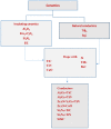
Classification of ceramics materials based on conductivity. (Reproduced with permission from [61]).
Figure 6
Figure 6
Electrical conductivity of materials [55].
Figure 7
Figure 7
Machining principles of EDM [55].
Figure 8
Figure 8
Comparison between crater dimensions in (a) conventional EDM (left) and (b) micro-EDM (right) (Reproduced with permission from [51]).
Figure 9
Figure 9
Thermal spalling effect on ceramic. (Reproduced with permission from [79]).
Figure 10
Figure 10
(a) Topography of ZrO2–TiN by wire EDM (V = 120 V, pulse on = 2.4 µs, pulse off = 15 µs); (b) Topography of Al2O3–SiCW–TiC by die sinking EDM in oil (high energy) (V = 250 V, i = 72 a, pulse on = 7.5 µs, pulse off = 18 µs); (c) Topography of Si3N4–TiN by Wire EDM (V = 160 V, pulse on = 2.8 µs, pulse off = 2.3 µs). (Reproduced with permission from [84]).
Figure 11
Figure 11
(a) Electrical resistivity of TiN/Si3N4 composites as function of TiN content (b) 40 vol. % small TiN/Si3N4; large white areas represent TiN while gray regions indicate Si3N4 (c) 700 µm depth and 70 µm dia. hole machined by Micro EDM. (Reproduced with permission from [97]).
Figure 11
Figure 11
(a) Electrical resistivity of TiN/Si3N4 composites as function of TiN content (b) 40 vol. % small TiN/Si3N4; large white areas represent TiN while gray regions indicate Si3N4 (c) 700 µm depth and 70 µm dia. hole machined by Micro EDM. (Reproduced with permission from [97]).
Figure 12
Figure 12
Cross-sectional scanning electron microscope (SEM) micrographs of EDM and treated surfaces of Al2O3/TiC ceramic composite (a) EDM; (b) treated by abrasive blasting; (c) treated by ultrasonic machining. (Reproduced with permission from [107]).
Figure 13
Figure 13
Schematic model for (a) conventional EDM and (b) carbon nanofiber assisted micro EDM, (c) machined surface at machining depth of 20 μm with 0.06 g/L carbon nanofibers. (Reproduced with permission from [47]).
Figure 14
Figure 14
Machined surface at stray capacitance but different levels of voltage with carbon nanofibers addition: (a) 60 V (b) 80 V (c) 100 V. (Reproduced with permission from [110]).
Figure 15
Figure 15
SEM micrographs of micro-holes after machining time of 2 min with ultrasonic cavitation in (a) pure EDM oil and (b) carbon nanofibers mixed EDM oil. (Reproduced with permission from [111]).
Figure 16
Figure 16
Basic principle of EDM of non-conducting ceramics with an Assisting electrode. Reproduced with permission from [53].
Figure 17
Figure 17
Assisting electrode scheme for machining nonconductive ceramic materials [154].
Figure 18
Figure 18
Pulse shapes and corresponding surface topographies. (Reproduced with permission from [140]).
Figure 19
Figure 19
Cross-section views of samples machined by S-EDM: (a) relaxation pulse and (b) iso-energetic pulse. (Reproduced with permission from [140]).
Figure 20
Figure 20
Principle of ED milling. Reproduced with permission from [57].
Figure 21
Figure 21
Effect of tool polarity on (a) MRR (b) surface roughness. (Reproduced with permission from [57]).
Figure 22
Figure 22
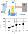
(a) Principle of gas-filled electro discharge and electrochemical compound machining (GFEECM), (b) Effect of peak current, (c) Effect of pulse duration on the MRR. (Reproduced with permission from [159]).
Figure 22
Figure 22
(a) Principle of gas-filled electro discharge and electrochemical compound machining (GFEECM), (b) Effect of peak current, (c) Effect of pulse duration on the MRR. (Reproduced with permission from [159]).
Figure 23
Figure 23
Basic cell configuration in electro-chemical discharge machining. Reproduced with permission from [162].

References

    1. Vereschaka A., Batako A., Krapostin A., Sitnikov N., Oganyan G. Improvement in reliability of ceramic cutting tool using a damping system and nano-structured multi-layered composite coatings. Procedia CIRP. 2017;63:563–568. doi: 10.1016/j.procir.2017.03.145. - DOI
    1. New Structural Materials Technologies: Opportunities for the Use of Advanced Ceramics and Composites, Report. Crediting UNT Libraries Government Documents Department; Gainesville, FL, USA: 1986. University of North Texas Libraries, Digital Library, digital.library.unt.edu.
    1. Claussen N. Fracture toughness of Al2O3 with an unstabilized ZrO2dispersed phase. J. Am. Ceram. Soc. 1976;59:49–51. doi: 10.1111/j.1151-2916.1976.tb09386.x. - DOI
    1. Wang J., Stevens R. Zirconia-toughened alumina (ZTA) ceramics. J. Mater. Sci. 1989;24:3421–3440. doi: 10.1007/BF02385721. - DOI
    1. Evans A. Engineering property requirements for high performance ceramics. Mater. Sci. Eng. 1985;71:3–21. doi: 10.1016/0025-5416(85)90202-2. - DOI

LinkOut - more resources