. 2019 Jan 8;116(2):670-678.
doi: 10.1073/pnas.1816724116. Epub 2018 Dec 26.

Bipolar switching by HCN voltage sensor underlies hyperpolarization activation

Affiliations

Bipolar switching by HCN voltage sensor underlies hyperpolarization activation

John Cowgill et al. Proc Natl Acad Sci U S A. .

Abstract

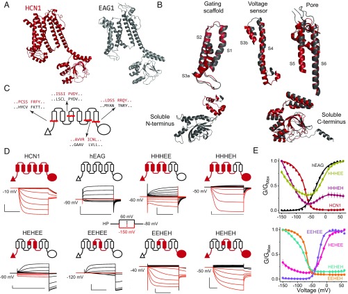
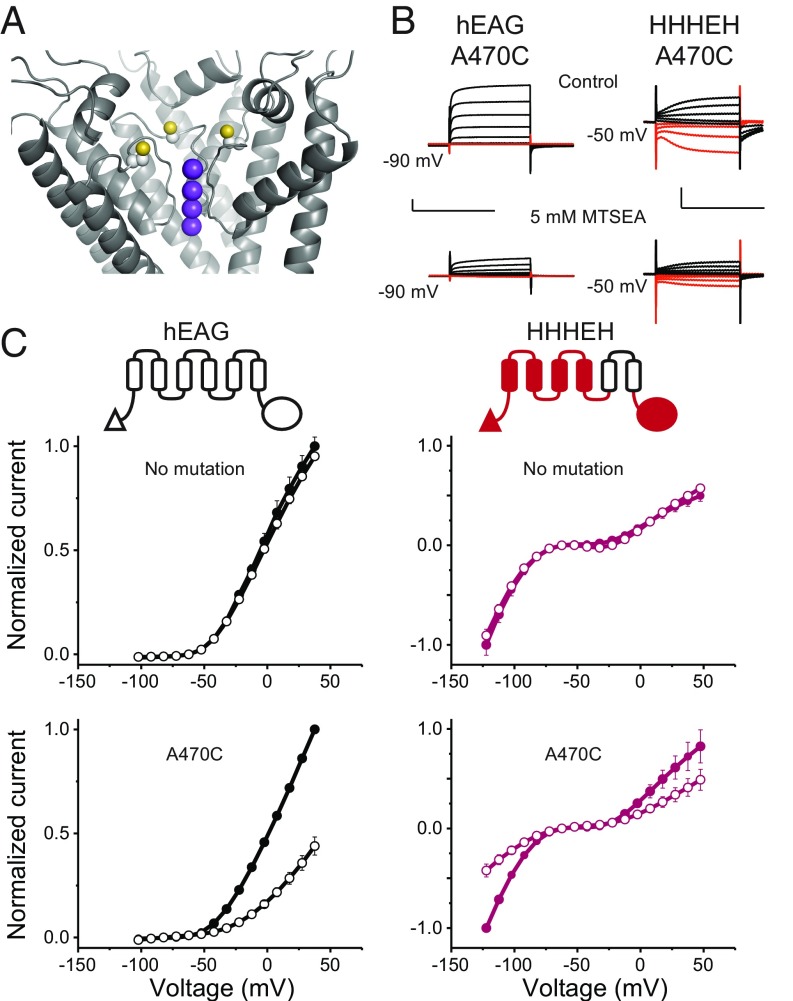
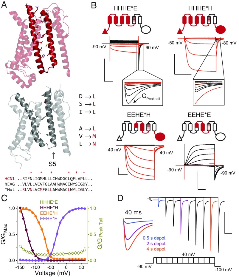
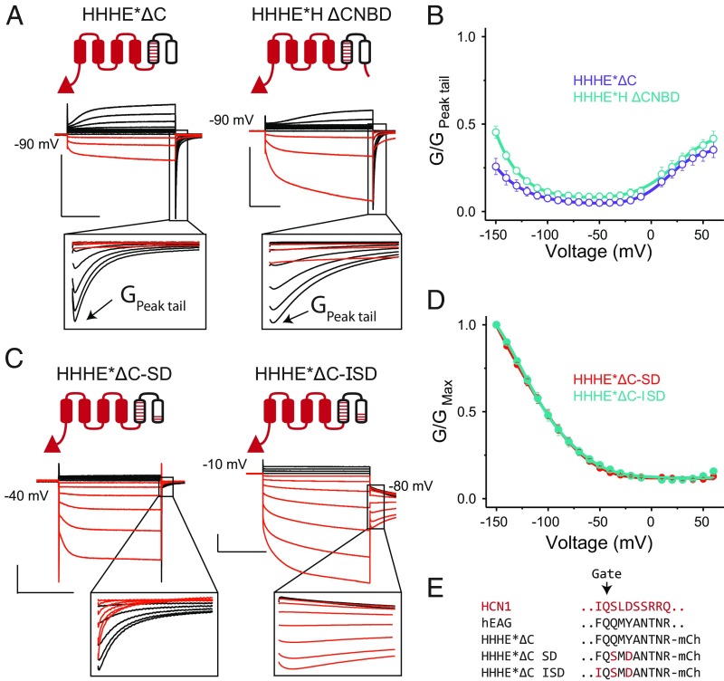
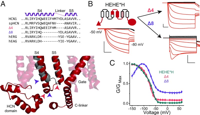
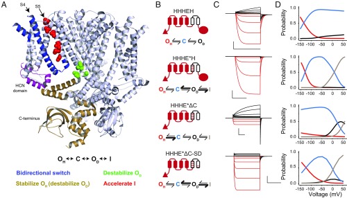
Despite sharing a common architecture with archetypal voltage-gated ion channels (VGICs), hyperpolarization- and cAMP-activated ion (HCN) channels open upon hyperpolarization rather than depolarization. The basic motions of the voltage sensor and pore gates are conserved, implying that these domains are inversely coupled in HCN channels. Using structure-guided protein engineering, we systematically assembled an array of mosaic channels that display the full complement of voltage-activation phenotypes observed in the VGIC superfamily. Our studies reveal that the voltage sensor of the HCN channel has an intrinsic ability to drive pore opening in either direction and that the extra length of the HCN S4 is not the primary determinant for hyperpolarization activation. Tight interactions at the HCN voltage sensor-pore interface drive the channel into an hERG-like inactivated state, thereby obscuring its opening upon depolarization. This structural element in synergy with the HCN cyclic nucleotide-binding domain and specific interactions near the pore gate biases the channel toward hyperpolarization-dependent opening. Our findings reveal an unexpected common principle underpinning voltage gating in the VGIC superfamily and identify the essential determinants of gating polarity.

Keywords: EAG; HCN; depolarization; hyperpolarization; ion channel.


Conflict of interest statement

The authors declare no conflict of interest.

Figures

Fig. 1.
Fig. 1.
HCN voltage-sensing domain is a bipolar switch. (A) Monomeric structures of hHCN1 and rEAG1 (the r-prefix denotes the rat homolog). The color coding for HCN1 (red) and EAG1 (black) is used throughout all figure panels. The N terminus of rEAG1 is omitted for clarity. (B) Structural alignment between hHCN1 and rEAG1 for the five modular segments used in generating the chimeric channels. (C) Cartoon representation showing the local sequence alignments of mHCN1 and hEAG1 around the junction points used in generating chimeric channels. (D) Cartoon representations of chimeric channels and representative traces for currents elicited in cut-open voltage clamp under symmetrical solutions (100 mM K+internal/100 mM K+external). Currents in response to depolarizing pulses are colored black, and responses to hyperpolarizing pulses are colored red for clarity. [Scale bars, 2 µA (vertical) and 500 ms (horizontal).] (E) Conductance–voltage curves for the parent and chimeric channels. Error bars are SEM from n = 5 (HHHEH and EEHEE), 6 (HEHEH), or 4 (all others) independent measurements.
Fig. 2.
Fig. 2.
Hyperpolarization- and depolarization-activated states share the same permeation pathway. (A) Location of the A470C mutation near the selectivity filter in the rEAG1 structure (yellow balls indicate sulfur atoms). Only three subunits are shown for clarity. Purple balls indicate positions of potassium ions as would be expected for EAG1 based on experimentally determined sites in the similar selectivity filter of Kv1.2/2.1. (B) Representative current traces for A470C mutants of EAG1 and HHHEH from two-electrode voltage clamp. Currents from EAG1-A470C were recorded in 100 mM Na+/5 mM K+, while the HHHEH-A470C was recorded under pseudosymmetric conditions using the same external solution as in Fig. 1. (B, Top) Traces represent initial recordings. (B, Bottom) Traces represent recordings following application of 5 mM MTSEA shown on the same scale. [Scale bars, 2 µA (vertical) and 500 ms (horizontal).] (C) Normalized current–voltage relationships for EAG (Left Top), HHHEH (Right Top), hEAG-A470C (Left Bottom), and HHHEH-A470C (Right Bottom) channels before (filled circles) and after (open circles) MTSEA addition, with error bars showing SEM for n = 2 (HHHEH), 3 (EAG1), 6 (EAG1-A470C), or 8 (HHHEH-A470C).
Fig. 3.
Fig. 3.
HCN1-like S4–S5 interface induces rapid inactivation upon depolarization. (A) Structures of the transmembrane regions of hHCN1 (Top) and rEAG1 (Middle) highlighting the S4–S5 interface. The sequence alignment indicates the S5 residues of the EAG1 pore that were mutated to their HCN1 equivalents to preserve S4–S5 interfacial interactions. (B) Cartoon representations of the mosaic chimeras and representative COVG current traces in symmetrical solutions (100 mM K+in/100 mM K+ex). Mosaic mutations are designated with an asterisk in the construct name. (B, Insets) Expanded view of tail currents displaying the hooked phenotype. (C) Steady-state G-V curves for mosaic channels depicted in B, with error bars representing SEM for n = 3 (HHHE*E and EEHE*H) or 4 (for all others). In the HHHE*E construct, the maximum conductance was observed in the tails upon repolarization to the indicated potentials. Therefore, the steady-state conductances were normalized to the maximum tail current (labeled as GPeak tail in B). The data points for HHHE*E are thus plotted as open symbols using a separate axis (Right) to emphasize this difference. This convention is used to highlight the fact that only a small fraction of channels are open at steady state. (D) Envelope-of-tails experimental protocol used with the HHHE*E construct to evaluate tail currents elicited by depolarizing +40-mV pulses of varying duration. Three traces for 0.5-, 2-, and 4-ms pulses are colored and reproduced at higher temporal resolution (Left). [Scale bars, 2 µA (vertical) and 500 ms (horizontal).]
Fig. 4.
Fig. 4.
Role of HCN1 C terminus and residues near the gate in regulating gating polarity. (A) Cartoons and representative COVG currents for truncation constructs that lack either the entire cytoplasmic C terminus (HHHE*ΔC) or CNBD (HHHE*H-ΔCNBD; residues following S478 of mHCN1 are removed from HHHE*H). (A, Insets) Expanded views of the tail currents to show the kinetic features more clearly. [Scale bars, 2 µA (vertical) 500 ms (horizontal) in all panels.] Tail pulse is at the holding potential. (B) G-V curves for the C-terminal truncations depicted in A, with error bars representing SEM for n = 3. For the same reasons noted in Fig. 3C for the HHHE*E construct, the steady-state conductance for both these truncations was normalized to their respective maximum tail currents. (C) Cartoons and representative COVG currents for the double and triple mutants of HHHE*ΔC. Note the Insets that show that the HHHE*ΔC-SD construct still exhibits hooked-tail currents on depolarizing pulses, while HHHE*ΔC-ISD does not. Tail pulse is at the holding potential unless noted otherwise. (D) G-V curves for the HHHE*ΔC-SD and HHHE*ΔC-ISD channels, with error bars showing SEM for n = 4 (HHHE*ΔC-SD) or 9 (HHHE*ΔC-ISD). (E) Sequences near the channel’s main gate in the S6 helix for mHCN1, hEAG1, HHHE*ΔC, and additional mutants made in the HHHE*ΔC background.
Fig. 5.
Fig. 5.
Extra length of the S4 helix is not essential for activation by hyperpolarization. (A, Top) Sequence alignments for some HCN- and EAG-like channels in the S4–S5 helix-turn-helix region. The resulting sequences of the S4 deletion mutants generated in the background of the HEHE*H construct (Δ4 and Δ8) are also indicated. (A, Bottom) HCN1 structure in the vicinity of the S4–S5 turn of HCN1 (red) is overlaid with that of EAG1 (gray). Note the extended length of the HCN1 S4 and its close proximity to the HCN domain and C linker, suggesting a potential for functionally critical interactions. Colored arrowheads indicate deletion boundaries in Δ4 (pink) and Δ8 (purple) mutants. (B) Representative COVG current traces for the HEHE*H construct and its two deletion derivatives. [Scale bars, 2 µA (vertical) and 500 ms (horizontal).] (C) G-V curves for the parent HEHE*H and deletion mutants, with error bars representing SEM for n = 4.
Fig. 6.
Fig. 6.
Voltage gating scheme for the CNBD family of channels. (A, Top) A unified state model for the CNBD family of ion channels. (A, Middle) A structural map highlighting the key elements involved in determining gating polarity in HCN1 channels. Only three out of four monomers are shown for clarity. The structural elements are colored according to their influence on each of the states shown in the unified gating model. The color scheme depicting which states are stabilized or destabilized by a particular element is shown below the structure. (B) Cartoon representations and models for several selected chimeras and mosaics. Bolded arrows indicate transitions that are favored by introduction of the HCN-like S4–S5 interface (HHHE*H), removal of the C terminus (HHHE*ΔC), or pore mutations near the gate (HHHE*ΔC-SD). (C) Simulated current traces from the model in response to the same pulse protocol applied in the electrophysiological recordings for each construct. Parameters for simulations can be found in SI Appendix, Table S1. (D) Probability vs. voltage curves for each state in the model measured as the probability of occupancy of each state over the final 10 ms of each test pulse. Probability curves for the hyperpolarized open state are colored red, the closed state is in blue, depolarized open state is in black, and inactivated state is in gray.

Similar articles

Cited by

References

    1. Bezanilla F. The voltage sensor in voltage-dependent ion channels. Physiol Rev. 2000;80:555–592. - PubMed
    1. Hodgkin AL, Huxley AF. Currents carried by sodium and potassium ions through the membrane of the giant axon of Loligo. J Physiol. 1952;116:449–472. - PMC - PubMed
    1. Ludwig A, Zong X, Jeglitsch M, Hofmann F, Biel M. A family of hyperpolarization-activated mammalian cation channels. Nature. 1998;393:587–591. - PubMed
    1. Santoro B, et al. Identification of a gene encoding a hyperpolarization-activated pacemaker channel of brain. Cell. 1998;93:717–729. - PubMed
    1. Brown HF, DiFrancesco D, Noble SJ. How does adrenaline accelerate the heart? Nature. 1979;280:235–236. - PubMed

Publication types

MeSH terms

Substances

LinkOut - more resources