. 2018 Dec 13:11:419-426.
doi: 10.2147/MDER.S181258. eCollection 2018.

Comparison of a micro-electro-mechanical system airflow sensor with the pneumotach in the forced oscillation technique

Affiliations

Comparison of a micro-electro-mechanical system airflow sensor with the pneumotach in the forced oscillation technique

Xiaohe K Xu et al. Med Devices (Auckl). .

Abstract

Purpose: This study supports the use of thin-film micro-electro-mechanical system (MEMS) airflow sensors in the forced oscillation technique.

Materials and methods: The study employed static testing using air flow standards and computer-controlled sound attenuations at 8 Hz. Human feasibility studies were conducted with a testing apparatus consisting of a pneumotach and thin-film MEMS air flow sensors in series. Short-time Fourier transform spectra were obtained using SIGVIEW software.

Results: Three tests were performed, and excellent correlations were observed between the probes. The thin-film MEMS probe showed superior sensitivity to higher frequencies up to 200 Hz.

Conclusion: The results suggest that lower-cost thin-film MEMS can be used for forced oscillation technique applications (including home care devices) that will benefit patients suffering from pulmonary diseases such as asthma, COPD, and cystic fibrosis.

Keywords: airway resistance; glottis closure; pulmonary disease; pulmonary impedance; short-time Fourier transform.


Conflict of interest statement

Disclosure CEF and REC are the owners of Feather Sensors, LLC, and XKX and SLM were employees of Feather Sensors, LLC at the time of this work. BPH was a graduate student of KRL (Boston University) during this work. The authors report no other conflicts of interest in this work.

Figures

Figure 1
Figure 1
Test apparatus used for the dynamic oscillatory studies. Notes: A 10” sub-woofer produced forced pressure 8 Hz oscillations. A differential pressure transducer was used to measure pressure fluctuations. Flow was measured simultaneously with a thin-film sensor and a screen pneumotach. An inertance tube provided a renewed air supply to the subject as well as a resistive element needed to pressure balance the system.
Figure 2
Figure 2
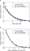
Steady state responses comparing the thin-film sensor with a pneumotach. Notes: (A) Responses of both the sensors at various computer-controlled sound levels. (B) The responses using standard airway resistors (Hans Rudolph) in series with the two probes. Both the sensor outputs decrease smoothly with increasing resistance up to 1,000 cm H2O s/L. Abbreviation: Log10, log 10 of the airflow resistor.
Figure 3
Figure 3
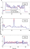
Absolute impedances (Z) for three 8 Hz FOT trials using human subjects with the thin-film and pneumotach in series. Notes: (A) and (B) Subjects were unrehearsed and represent equipment readjustments as well as tidal (normal) breathing. (C) The subject was instructed to breath normally in conjunction with two deep inhalations during the run with cheeks clamped (Figure 1). Abbreviations: FOT, forced oscillation technique; MEMS, micro-electromechanical system.
Figure 4
Figure 4
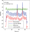
Computed raw phases for the pneumotach and thin-film MEMS sensor during Trial 3. Notes: The computed phase is the retardation with respect to the pressure sensor. A sharp decrease in the phase is observed at the maximum of deep inhalation. The difference curve is plotted at the top. The least squares fit to the difference data are shown as the dotted line with virtually no slope during the experiment. Abbreviation: MEMS, micro-electro-mechanical system.
Figure 5
Figure 5
Comparison of the airway resistance (R) during Trial 3 for the pneumotach and thin-film sensor connected in series. Notes: Simultaneous airway resistances for both the probes during a controlled trial with normal inhalations and two deep breaths. Glottis #1 and #2 refer to glottic closures observed during DI#1 and #2. The sensitivity for the thin-film MEMS probe is significantly larger during the DIs due to higher frequency response during these short-term events. Abbreviations: DI, deep inhalation; MEMS, micro-electro-mechanical system.
Figure 6
Figure 6
Cross correlation of airway resistance (R) between the pneumotach and the thin-film MEMS sensor during Trial 3. Notes: (A) Total comparison of data including glottic closures. During glottic closure, the thin-film sensor shows higher resistances compared to the pneumotach, and, therefore, loop trajectories appear above the diagonal (blue loops). The coefficient of determination (R2) was 0.961, and the number of observations was 7,393. (B) Segments corresponding to glottic closures (loops) in Trial 3 are removed. The number of observations was 6,973 and R was 0.986. Abbreviation: MEMS, micro-electro-mechanical system.
Figure 7
Figure 7
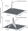
Short-time Fourier transform spectra of the two types of probes used in this study. Notes: The sound frequency from the sub-woofer speaker is ramped from 2 to 250 Hz in 30 seconds. An ideal response is a steep narrow wall along the diagonal as time increases. (A) The Hans Rudolph pneumotach showed a limited response up tô45 Hz. (B) The thin-film MEMS probe similar to the one used in this study showed an almost constant response up to ~200 Hz and then fell off. Both the graphs (A) and (B) display frequency harmonics. The pneumotach (A) shows a small 3 Ω harmonic indicating a small deviation from sinusoidal behavior. The thin-film MEMS sensor (B) shows harmonics at 2, 3 (most prominent), 4, and 5 Ω due to the larger degree of non-sinusoidal sensor output. Abbreviation: MEMS, micro-electro-mechanical system.

References

    1. Dubois AB, Brody AW, Lewis DH, Burgess BF. Oscillation mechanics of lungs and chest in man. J Appl Physiol. 1956;8(6):587–594. - PubMed
    1. Bates JH. Lung Mechanics: An Inverse Modeling Approach. Cambridge: Cambridge University Press; 2009.
    1. Lutchen KR, Suki B. Understanding pulmonary mechanics using the forced oscillations technique. In: Khoo MCK, editor. Bioengineering Approaches to Pulmonary Physiology and Medicine. Boston, MA: Springer; 1996. pp. 227–253.
    1. Strömberg NO, Grönkvist MJ. Improved accuracy and extended flow range for a Fleisch pneumotachograph. Med Biol Eng Comput. 1999;37(4):456–460. - PubMed
    1. Kreit JW, Sciurba FC. The accuracy of pneumotachograph measurements during mechanical ventilation. Am J Respir Crit Care Med. 1996;154(4 Pt 1):913–917. - PubMed

LinkOut - more resources