Review
. 2018 Dec 21;4(1):56-70.
doi: 10.1016/j.bioactmat.2018.12.003. eCollection 2019 Mar.

Additive manufacturing technology for porous metal implant applications and triple minimal surface structures: A review

Affiliations
Review

Additive manufacturing technology for porous metal implant applications and triple minimal surface structures: A review

Li Yuan et al. Bioact Mater. .

Erratum in

Abstract

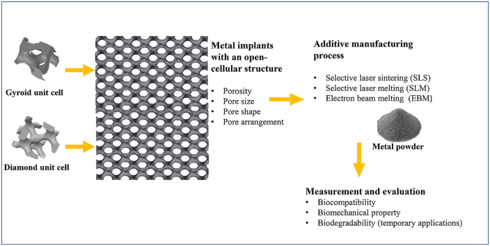
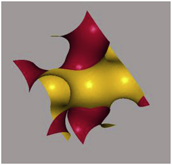
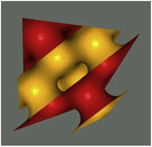
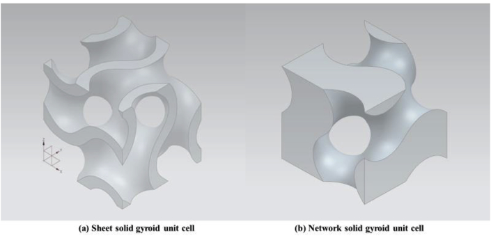
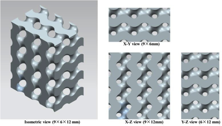
Recently, the fabrication methods of orthopedic implants and devices have been greatly developed. Additive manufacturing technology allows the production of complex structures with bio-mimicry features, and has the potential to overcome the limitations of conventional fabrication methods. This review explores open-cellular structural design for porous metal implant applications, in relation to the mechanical properties, biocompatibility, and biodegradability. Several types of additive manufacturing techniques including selective laser sintering, selective laser melting, and electron beam melting, are discussed for different applications. Additive manufacturing through powder bed fusion shows great potential for the fabrication of high-quality porous metal implants. However, the powder bed fusion technique still faces two major challenges: it is high cost and time-consuming. In addition, triply periodic minimal surface (TPMS) structures are also analyzed in this paper, targeting the design of metal implants with an enhanced biomorphic environment.

Keywords: Additive manufacturing; Porosity; Powder bed fusion; TPMS structures.


Figures

Image 1
Graphical abstract
Fig. 1
Fig. 1
Ti scaffolds with 70% porosity and different ranges of pore sizes [41].
Fig. 2
Fig. 2
Cell viability of the porous Ti scaffolds with 70% porosity and different pore sizes after cell culture for 1, 3, 7 and 12 days [41].
Fig. 3
Fig. 3
Schematic of an SLM machine [84].
Fig. 4
Fig. 4
SEM images of Ti—6Al—4V gyroid lattice surfaces fabricated by SLM: (a) and (b) as-built, (c) and (d) after post treatments (heat treatment and sandblasting) [88].
Fig. 5
Fig. 5
SEM images of Ti—6Al—4V gyroid lattices surfaces fabricated by EBM: (a) as-built, (b) after post treatment of ceramic blasting [20].
Fig. 6
Fig. 6
(a) Schematic of an EBM machine and (b) its processing chamber [91,92].
Fig. 7
Fig. 7
Gyroid unit cell with ±0.6 offset.
Fig. 8
Fig. 8
Gyroid surface following mathematical equation (3): in order to generate a basic unit cell of a gyroid surface, the x, y and z spatial directions are in the interval length of 2π, where x, y, z = [-π, π] and a=0.
Fig. 9
Fig. 9
Diamond surface following mathematical equation (4): in order to generate a basic unit cell of a diamond surface, the x, y and z spatial directions are in the interval length of 2π, where x, y, z = [-π, π] and a=0.
Fig. 10
Fig. 10
3D CAD gyroid unit cells: (a) 3 mm sheet solid gyroid unit cell with 0.3 mm offset thickness and (b) 3 mm network solid gyroid unit cell at 50% volume fraction.
Fig. 11
Fig. 11
A block of a 3D CAD gyroid scaffold in different views (constituted by 3 mm network solid gyroid unit cell).
Fig. 12
Fig. 12
Gyroid surfaces and network-based on gyroid unit cell with different offset (α) values: (a) a 3 mm network-based gyroid structure in an 3 × 3 × 3 mm cubic; (b-1) gyroid surface without offset, (b-2) network-based gyroid unit cell without offset, (c-1) gyroid surface with offset = −0.6, (c-2) network-based gyroid unit cell with offset = −0.6, (d-1) gyroid surface with offset = −1.31, (d-2) network-based gyroid with offset = −1.31, (e) gyroid surface with offset = −1.41, (f) gyroid surface with offset = −1.42, (g) gyroid surface with offset = −1.49.
Fig. 13
Fig. 13
Schematic of a normal pore and a deformed pore.

Similar articles

Cited by

References

    1. Goudie E.B., Robinson C., Walmsley P., Brenkel I. Changing trends in total knee replacement. Eur. J. Orthop. Surg. Traumatol. 2017;27:539–544. doi: 10.1007/s00590-017-1934-8. - DOI - PMC - PubMed
    1. Losina E., Katz J.N. Total knee arthroplasty on the rise in younger patients: are we sure that past performance will guarantee future success. Arthritis Rheum. 2012;64:339–341. doi: 10.1002/art.33371. - DOI - PMC - PubMed
    1. Prasad K., Bazaka O., Chua M., Rochford M., Fedrick L., Spoor J., Symes R., Tieppo M., Collins C., Cao A., Markwell D., Ostrikov K., Bazaka K. Metallic biomaterials: current challenges and opportunities. Materials. 2017;10:884. doi: 10.3390/ma10080884. - DOI - PMC - PubMed
    1. Palmer L.C., Newcomb C.J., Kaltz S.R., Spoerke E.D., Stupp S.I. Biomimetic systems for hydroxyapatite mineralization inspired by bone and enamel. Chem. Rev. 2008;108:4754–4783. https://pubs.acs.org/doi/abs/10.1021/cr8004422 - DOI - PMC - PubMed
    1. Goods Administration Therapeutic. 2011. Australian Regulatory Guidelines for Medical Devices.https://www.tga.gov.au/sites/default/files/devices-argmd-01.pdf

LinkOut - more resources