. 2019 Jan;565(7739):361-365.
doi: 10.1038/s41586-018-0823-6. Epub 2019 Jan 2.

A wireless closed-loop system for optogenetic peripheral neuromodulation

Affiliations

A wireless closed-loop system for optogenetic peripheral neuromodulation

Aaron D Mickle et al. Nature. 2019 Jan.

Abstract

The fast-growing field of bioelectronic medicine aims to develop engineered systems that can relieve clinical conditions by stimulating the peripheral nervous system1-5. This type of technology relies largely on electrical stimulation to provide neuromodulation of organ function or pain. One example is sacral nerve stimulation to treat overactive bladder, urinary incontinence and interstitial cystitis (also known as bladder pain syndrome)4,6,7. Conventional, continuous stimulation protocols, however, can cause discomfort and pain, particularly when treating symptoms that can be intermittent (for example, sudden urinary urgency)8. Direct physical coupling of electrodes to the nerve can lead to injury and inflammation9-11. Furthermore, typical therapeutic stimulators target large nerve bundles that innervate multiple structures, resulting in a lack of organ specificity. Here we introduce a miniaturized bio-optoelectronic implant that avoids these limitations by using (1) an optical stimulation interface that exploits microscale inorganic light-emitting diodes to activate opsins; (2) a soft, high-precision biophysical sensor system that allows continuous measurements of organ function; and (3) a control module and data analytics approach that enables coordinated, closed-loop operation of the system to eliminate pathological behaviours as they occur in real-time. In the example reported here, a soft strain gauge yields real-time information on bladder function in a rat model. Data algorithms identify pathological behaviour, and automated, closed-loop optogenetic neuromodulation of bladder sensory afferents normalizes bladder function. This all-optical scheme for neuromodulation offers chronic stability and the potential to stimulate specific cell types.


Conflict of interest statement

Conflict of Interest:

JAR and RWG are co-founders of Neurolux, a company that manufactures wireless optoelectronic devices. The device described here uses similar technology, however is distinct from the current Neurolux portfolio.

Figures

Extended Data Figure 1.
Extended Data Figure 1.. Demonstration of opto-electronic stimulation and sensing module features and implantation of the whole CLOC system.
a) Demonstration of strain gauge placement on a mimic bladder illustrating the how the two silicone bands wrap around the bladder and how stretch is exerted on the strain gauge as the bladder expands. b) Detailed surgical procedure for implantation of the wireless closed-loop optogenetics-based system for peripheral neuromodulation. The strain gauge is placed on the bladder (1), using curved forceps, the lower band is pulled under the bladder and wrapped back on top of the opto-electronic stimulation and sensing module (2). Kwik-Sil is then applied to secure the lower band to the top of opto-electronic stimulation and sensing module (3). The upper band is then wrapped around the largest part of the bladder dome and the buckle secured. Then a small suture is placed through the buckle into the bladder smooth muscle layer to secure the upper band to the bladder (4). The bladder is then placed back in the abdominal cavity (5) and muscle layers closed with suture (6). The WCP is inserted between the skin and the muscle layer (6) and the skin is closed with surgical staples (8 and 9).
Extended Data Figure 2.
Extended Data Figure 2.. Computational/experimental studies of the bladder strain gauge and material properties of rat bladder.
a) Schematic illustration of a strain gauge (SG), portion of the opto-electronic stimulation and sensing module. The right panel represents a cross-sectional side view of the device components at the level of the dashed line shown in the left panel. b) Image of a rat bladder (left) and digitally manipulated version (right) to allow measurements of the volumetric changes in size during cystometry. c) Graph of changes in bladder size (red) and changes in strain gauge resistance (black). d) Fractional change in resistance of the strain gauge as function uniaxial tensile strain. e) Fractional change in resistance under 1000 cycles of stretching to a maximum strain of 20 %. f) Uniaxial strain-stress curve of carbon black-silicone composite and the undoped neat silicone. g) Length and width of the bladder measured using Vernier caliper, at different inner pressures. h) Representative optical image of a rat bladder at different inner pressure: 3.2 mmHg (left) and 18.4 mmHg (right) (Ruler marks 1 mm). i) Simulation results for the width and length of the bladder based on measured values of the inner pressure and the initial length and width.
Extended Data Figure 3.
Extended Data Figure 3.. Optical and Thermal characteristics of the μ-ILEDs.
a) Schematic illustration of the μ-ILED portion of the opto-electronic stimulation and sensing module. b) Electrical and optical characteristics of pair of μ-ILEDs. c) Measured power associated with penetration of light from a μ-ILED through the whole rat bladder (both layers) at fully inflated and empty states, additional calculations were performed on single bladder layer relaxed and manually stretched. (performed in 3 biologically independent samples, mean ± SEM) d) Results from in vivo testing of the temperature associated with operation of the μ-ILEDs for an hour. e) The material properties in the model. f) Simulated results for the temperature associated with operation of the μ-ILEDs with and without the stainless-steel substrate. g) The schematic illustration of OESS module embedded in the tissue with dimensions of 30×30×30 mm3 in FEA model. h) The effect of number of elements in FEA model on the temperature increment in vivo with power of 70 mW for steady state analysis.
Extended Data Figure 4.
Extended Data Figure 4.. Layout and operation of the wireless control and power (WCP) module.
a) Layout and component information for the WCP module. b) Normalized wireless power distribution, in dB, inside the rat cage (30 cm × 60 cm) at heights of 0 and 5 cm from the ground. c) Normalized wireless power received, in dB, at different out-of-plane orientation angles of the receiver antenna relative to the transmission antenna, for positions at corner and center of the cage. d) A plot of the supercapacitor voltage, which is proportional to the stored energy, as a function of time after deactivating the transmission antenna while the system is otherwise fully operational.
Extended Data Figure 5.
Extended Data Figure 5.. Effect of opto-electronic stimulation and sensing module implantation or sham surgery on bladder cystometric properties, histology and animal health.
a) Representative traces of anesthetized constant infusion (0.1 ml/min) cystometric voiding from sham and CLOC device implanted animals. b) Quantification of peak pressure (PP), base pressure (BP), and threshold pressure (TP) indicated no significant differences between sham and device groups. The data indicates no significant differences in intercontraction interval (ICI) or bladder compliance (Δvolume/Δpressure) between sham and device animals (n=6 for all groups; all data represented ± SEM) c) Representative H&E staining of bladder tissue in direct contact with the strain gauge and the full CLOC device implanted and sham-surgery animals (No overt histological differences were observed in these tissues (n=3 for each group in biologically independent samples with similar results). Scale bar is 100 μm. Examples (scale bar 250 μm) (d) and quantification (e) of bladder thickness, comparing device implanted animals to sham. f) Sham-surgery and device implanted animals gained similar amounts of weight on postoperative day (POD) 7. g) Animals from both groups ran similar distances in a novel arena (42 × 42 × 30 cm). h) CLOC system implantation did not significantly affect measurements of gait, including average run speed, run speed variation, step sequence regularity and steps per second (cadence) (n = 5 for all groups (panel d-f); all data represented ± SEM).
Extended Data Figure 6.
Extended Data Figure 6.. Bladder cystometric properties and markers of inflammation are not significantly altered by injection of HSV-eYFP compared to sham surgery animals.
a) Representative traces of constant infusion (0.1 ml/min) anesthetized (urethane) cystometric voiding from sham-injected and virus-injected (HSV-CMV-eYFP) rats. b) Quantification of peak pressure (PP), base pressure (BP), and threshold pressure (TP) indicated no significant differences between sham-injected and virus-injected groups (n=4 animals per group; all data represented ± SEM). There were no significant differences in intercontraction interval (ICI) (c) or bladder compliance (Δvolume/Δpressure) (d) between sham-injected and virus-injected rats. No significant difference was observed in average number of mast cells (e) or degree of degranulation (f), indicating that no overt inflammatory response is detected in bladders injected with HSV-eYFP vs sham surgery 7 days after injection (n=4 animals per group; all data represented ± SEM)
Extended Data Figure 7.
Extended Data Figure 7.. Activation of Arch, in cultured bladder-projecting rat DRG neurons and human DRG reduces neuronal excitability.
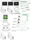
a) Example of a neuron transduced with HSV-Arch-eYFP (green) and identified as a neuron that projects to bladder based on labeling with DiI (red) following DiI injection in the bladder wall (7 days prior) (scale bar 20 μM; similar to results obtained from three independent experiments). b) Representative traces of DRG neuron firing properties in response to step current injection current 1-4x threshold with (green) and without (black) green light illumination (530 nm) (similar to results obtained from three independent cultures). Quantification of Arch-induced current amplitude in voltage clamp (c) and membrane hyperpolarization in current clamp (d) at peak and steady state. e) Quantification of action potential (AP) frequency with and without illumination demonstrating a light dependent inhibition of AP firing. (a-e: no light n=13, 3.3 mW/mm2 n= 8, 10 mw/mm2 n=5 different cells, from 3 biologically independent cultures; all data represented mean ± SEM; One-way Anova with Dunnett’s multiple comparisons test; * p<0.05). f) Example of a patched human DRG neuron transduced with HSV-Arch-eYFP. g) Example voltage clamp trace demonstrating the photocurrent elicited by green light (530 nm). h) Representative current clamp trace demonstrating the ability of Arch to inhibit neuronal firing in response to 3× threshold current injection. i) Current clamp traces with (green) and without (black) activation of Arch, showing a reduction in action potential firing in response to 1-4x threshold ramp currents. Quantification of light-induced current in voltage clamp (j) and hyperpolarization in current clamp (k) at peak and steady state (SS) in Arch-expressing human DRG neurons. Panels f-h have been repeated in 5 different cells from one culture, with similar biological results. The cartoon images from panels (a) and (f) are from Servier Medical Art by Servier (https://smart.servier.com/), and are covered by Creative Commons 3.0 attribution license (https://creativecommons.org/licenses/by/3.0/). No changes were made to the original artwork.
Extended Data Figure 8.
Extended Data Figure 8.. Effect of Arch activation and CYP-induced bladder dysfunction on voiding properties.
Representative traces (a) and grouped data (b) that demonstrate a significant increase in cystometric inter-contraction interval (ICI) during green light illumination in HSV-Arch injected animals compared to HSV-eYFP injected controls, as defined by the strain gauge and pressure recordings. (n=4 rats/group; *p<0.05, unpaired t test). c) Activation of Arch in bladder sensory afferents does not affect base, threshold or peak pressure. No changes were observed during bladder illumination in base pressure, threshold pressure or peak pressure in anesthetized (urethane) cystometry (0.1 ml/min) comparing HSV-Arch-eYFP injected rats to HSV-eYFP injected rats. (n=4; all data represented mean ± SEM). d) Effect of Arch activation on normal voiding in awake, non-anesthetized rats. Illumination of HSV-Arch injected bladders (Arch = HSV-Arch-eYFP/LED-ON) did not significantly alter number of voids or time to first void compared to HSV-eYFP (eYFP = HSV-eYFP injected/LED-ON) and HSV-injected/ No LED groups in non-inflamed animals. (n=6; all data represent mean ± SEM). e) Rats injected with CYP have significantly more voids and less time to 1st void during the 3 hours after CYP injection as compared to baseline. (n=6; all data represented mean ± SEM; ** p<0.01). f) A single dose of CYP does not cause a significant increase in evoked visceral motor response (VMR). (n=8 saline, n=9 CYP animals; data represented mean ± SEM)
Extended Data Figure 9.
Extended Data Figure 9.. Automatic identification of voiding events from raw strain gauge data.
a) Diagram demonstrating the step-by-step process for identifying voids from raw strain gauge data. b) Quantification of the number of missed voids, false voids, false voids per hour and percent correct during 8 hours of recording at baseline and 8 hours after CYP using the void detection algorithm. (n=9 rat per group; data represented mean ± SEM). c) Percent change in void size after CYP (75 mg/kg) administration (n=11 biologically independent animals; mean ± SEM). d) In-vitro demonstration of the void volume threshold component of the closed loop algorithm. With a threshold of 15 au (20% fractional change of resistance), the closed loop system did not activate when the void volumes were larger than 15 au (right), while the closed loop system was triggered and turned on the LEDs when void sizes were smaller than 15 au (left). e) Demonstration of prolonged battery-free recording (repeated twice in independent animals with similar results)
Extended Data Figure 10.
Extended Data Figure 10.. Results from in vitro testing of the strain gauge.
a) Photograph of the in vitro setup, including a strain gauge on a mimic bladder (Ecoflex-0030) in saline solution (PH 7.4), a syringe pump (0.175 μl/min) to control the size of the bladder, a function generator to supply power (7 Hz, 10 V) for external vibration, a pressure gauge and digital multimeter to monitor pressure in the bladder. b) Change in resistance of strain gauge on a mimic bladder during inflation at an inner pressure of 1 kPa, in otherwise ambient laboratory condition. c) Similar changes during inflation with saline solution at 1 kPa, in the presence of externally induced vibration. d) Change in resistance change of the strain gauge under the various condition; vibration, stirring, and poking.
Figure 1.
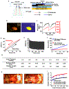
Figure 1.. Schematic illustrations and images of a fully implantable, soft optoelectronic system for wireless, closed-loop optogenetic modulation of bladder function.
a) The platform consists an opto-electronic stimulation and sensing (OESS) module, a low modulus, stretchable strain gauge (SG) with integrated microscale inorganic light emitting diodes (μ-ILEDs) that wraps around the bladder to monitor changes in its volume and to provide optogenetic stimulation to the neurons innervating the bladder. The wireless control/power (WCP) module records the response of the strain gauge, controls operation of the μ-ILEDs and provides power management. Wireless data communication to and from the WCP module relies on Bluetooth protocols and a tablet computer. Power is delivered wirelessly via resonant magnetic coupling through a dual antenna transmitter. b) Picture of opto-electronic stimulation and sensing module including the strain gauge, the μ-ILEDs and wireless base station for data communication. c) Schematic illustration that highlights the placement of the strain gauge around the bladder, with an implanted, wired connection to the WCP module subcutaneously implanted anterior to the bladder. Images created by Janet Sinn-Hanlon, The DesignGroup@VetMed, University of Illinois at Urbana-Champaign. d) Rat implanted with the complete system (a green μ-ILED indicator on the WCP module verifies function). e) Computed tomography image of a device implanted for 1 month.
Figure 2.
Figure 2.. Electrical and mechanical properties of the opto-electronic stimulation and sensing module.
a) Schematic illustration of the opto-electronic stimulation and sensing module. b) Dynamic mechanical analysis of a strain gauge (SG) with comparison to a simulated stress-strain curve of bladder from the empty state. c) Simulated radius of a bladder during expansion with and without an integrated opto-electronic stimulation and sensing module. d) Images (left) of a strain gauge and a pair of μ-ILEDs wrapped around the outer surface of the rat bladder, in contracted and expanded states. Computed distributions of strain (right) for a strain gauge integrated with a spheroidal model of the rat bladder. (Scale bar: 2.5mm) e) Acute rat bladder cystometry before and after placement of the opto-electronic stimulation and sensing module, demonstrating no discernable alterations to intravesical pressure. f) Schematic illustration of the implantable wireless control/power module. g) Operational block diagram of the overall system design. (Rx-receiving, Tx-transmitting)
Figure 3.
Figure 3.. Optogenetic modulation of bladder function.
a) Time dependence of strain gauge data (60 point running average) collected from a freely moving rat implanted with a CLOC system, showing rapid decreases in resistance that correlate with micturition events measured by a computerized balance in a micturition cage. b) Expression of Arch-eYFP in bladder afferent endings and cell bodies of the dorsal root ganglion 7 days after injection of HSV-Arch-eYFP into the bladder wall. c) Raster plot representing voiding of individual animals (horizontal rows) before and after CYP in HSV-eYFP LED-ON, HSV-Arch LED-ON and virus-injected LED-OFF groups before and after CYP. d) Quantification of mean number of voids 3 hours after CYP and time to 1st void after CYP injection in all groups. (n=6 rats/group; *p<0.05, **p<0.01; Two-way ANOVA with Tukey’s multiple comparison test; Error bars represent Mean±SEM).
Figure 4.
Figure 4.. Closed-loop optogenetic control of bladder function.
a) Flow chart of the steps implemented in the closed-loop software to activate the μ-ILED when voiding becomes hyperactive. b) Demonstration of closed-loop μ-ILED activation, initiated at an average of 265 min post-injection after injection of CYP with corresponding decrease in voiding events in HSV-Arch-eYFP injected rats compared to HSV-eYFP control injected rats.

Comment in

References

Refrences:

    1. Birmingham K et al. Bioelectronic medicines: a research roadmap. Nature reviews. Drug discovery 13, 399–400, doi:10.1038/nrd4351 (2014). - DOI - PubMed
    1. Cameron T Safety and efficacy of spinal cord stimulation for the treatment of chronic pain: a 20-year literature review. Journal of neurosurgery 100, 254–267 (2004). - PubMed
    1. De Ferrari GM et al. Chronic vagus nerve stimulation: a new and promising therapeutic approach for chronic heart failure. European heart journal 32, 847–855, doi:10.1093/eurheartj/ehq391 (2011). - DOI - PubMed
    1. de Groat WC & Tai C Impact of Bioelectronic Medicine on the Neural Regulation of Pelvic Visceral Function. Bioelectronic medicine 2015, 25–36 (2015). - PMC - PubMed
    1. Famm K, Litt B, Tracey KJ, Boyden ES & Slaoui M Drug discovery: a jump-start for electroceuticals. Nature 496, 159–161, doi:10.1038/496159a (2013). - DOI - PMC - PubMed

Method References:

    1. Christian AG & Ellis M Low-cost carbon thick-film strain sensors for implantable applications. Journal of Micromechanics and Microengineering 20, 095028 (2010).
    1. Lu N, Lu C, Yang S & Rogers J Highly Sensitive Skin-Mountable Strain Gauges Based Entirely on Elastomers. Advanced Functional Materials 22, 4044–4050, doi:doi:10.1002/adfm.201200498 (2012). - DOI
    1. Damaser MS & Lehman SL Does it matter, the shape of the bladder? Neurourology and urodynamics 12, 277–280 (1993). - PubMed
    1. Korkmaz I & Rogg B A simple fluid-mechanical model for the prediction of the stress-strain relation of the male urinary bladder. Journal of biomechanics 40, 663–668, doi:10.1016/j.jbiomech.2006.02.014 (2007). - DOI - PubMed
    1. Kelly P Mechanics Lecture Notes: An introduction to Solid Mechanics. Available from http://homepages.engineering.auckland.ac.nz/~pkel015/SolidMechanicsBooks..., p 185–194 (2018).

Publication types