Review
. 2018 Apr 4;8(2):139-155.
doi: 10.1007/s13534-018-0062-7. eCollection 2018 May.

Clinical photoacoustic imaging platforms

Affiliations
Review

Clinical photoacoustic imaging platforms

Wonseok Choi et al. Biomed Eng Lett. .

Abstract

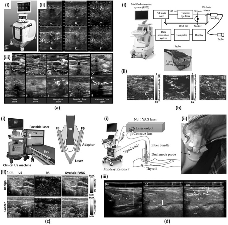
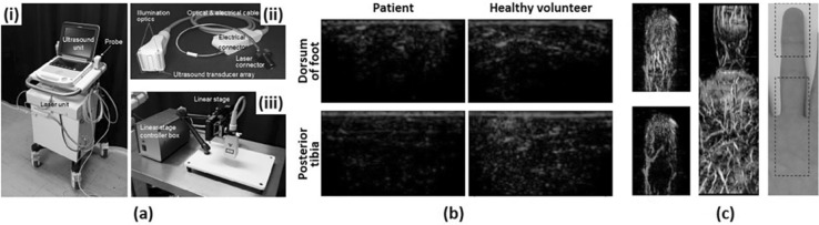
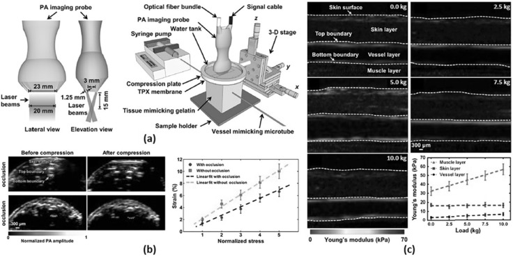
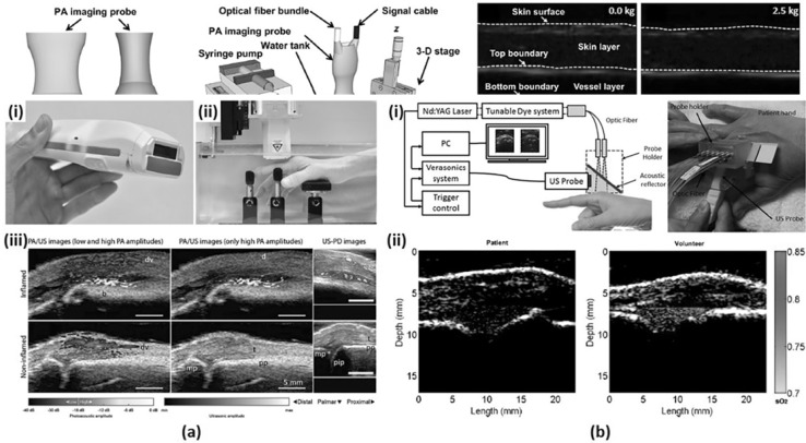
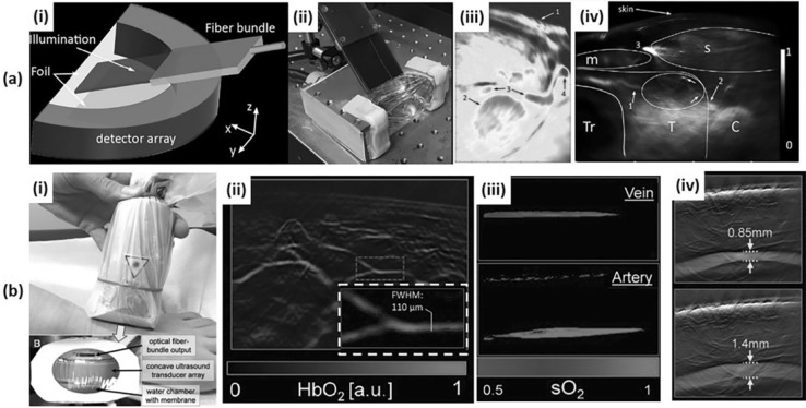
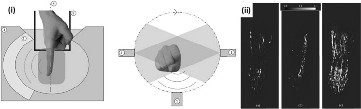
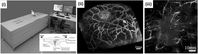
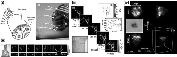
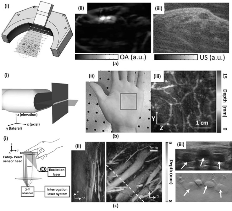
Photoacoustic imaging (PAI) is a new promising medical imaging technology available for diagnosing and assessing various pathologies. PAI complements existing imaging modalities by providing information not currently available for diagnosing, e.g., oxygenation level of the underlying tissue. Currently, researchers are translating PAI from benchside to bedside to make unique clinical advantages of PAI available for patient care. The requirements for a successful clinical PAI system are; deeper imaging depth, wider field of view, and faster scan time than the laboratory-level PAI systems. Currently, many research groups and companies are developing novel technologies for data acquisition/signal processing systems, detector geometry, and an acoustic sensor. In this review, we summarize state-of-the-art clinical PAI systems with three types of the imaging transducers: linear array transducer, curved linear array transducer, and volumetric array transducer. We will also discuss the limitations of the current PAI systems and describe latest techniques being developed to address these for further enhancing the image quality of PAI for successful clinical translation.

Keywords: Clinical systems; Medical imaging; Optoacoustics; Photoacoustics; Ultrasound array transducer.


Conflict of interest statement

All authors declare to have no conflict of interests.This article does not contain any studies with human participants or animals performed by any of the authors.Not applicable.

Figures

Fig. 1
Fig. 1
a A duplex PA/US imaging system for in vivo breast cancer imaging. (i) A photograph of the system. (ii) A standard 6-on-1 PA image from a patient with invasive mixed ductal and lobular carcinoma. (iii) Exemplary images of minimum and maximum scores for five PA features. b A dual-modality PA/US imaging system for noninvasive SLN detection in breast cancer patients. (i) A schematic of the system. (ii) US, PA and co-registered US/PA images of SLN and needle. c A clinical PA/US imaging system for thyroid cancer imaging. (i) Photography of the system and a schematic of an integrated PA/US imaging probe. (ii) US, PA and overlaid PA/US images of benign and cancer cases. d A PA/US dual imaging system for human thyroid cancers. (i) A schematic of the system. (ii) A photograph of a dual-modality handheld probe. (iii) Color Doppler, US, and PA/US imaging results for a left lobe papillary thyroid cancer. All images were reproduced with permission from Refs. [, –55]. PA photoacoustic; US ultrasound; and SLN sentinel lymph node
Fig. 2
Fig. 2
a A PA/US imaging system for peripheral small-vessel imaging. (i) A photograph of the system. (ii) A photograph of a handheld type PA probe. (iii) A photography of a linear stage scanner for 3D image acquisition. b PA images of a diabetic foot patient and a healthy volunteer. c Overlaid PA–US Doppler and PA MAP images and a photograph of a human finger. All images were reproduced with permission from Ref. [30]. PA photoacoustic, US ultrasound, MAP maximum amplitude projection
Fig. 3
Fig. 3
a A schematic of VE-PAT. b VE-PAT images of a human finger without vessel occlusion before and after compression and with vessel occlusion before and after compression and corresponding strain–stress curve. c QPAE of the human arm at different loadings. All images were reproduced with permission from Refs. [56, 60]. VE-PAT vascular elastic photoacoustic tomography, QPAE quantitative photoacoustic elastography
Fig. 4
Fig. 4
a A dual modality PA/US system for synovitis imaging. (i) A photograph of a handheld PA/US probe. (ii) A sample positioner for human finger imaging. (iii) PA/US and US Doppler images of inflamed and non-inflamed contra-lateral joint. b A PA/US dual imaging system for inflammatory arthritis in the human joint. (i) A schematic and a photograph of the system. (ii) PA sO2 images of a patient’s MCP joint and a healthy volunteer’s MCP joint. All images were reproduced with permission from Refs. [31, 32]. PA photoacoustic, US ultrasound, sO2 oxygen saturation, MCP metacarpophalangeal
Fig. 5
Fig. 5
a An MSOT system for in vivo human neck imaging. (i) A schematic and (ii) a photograph of an MSOT imaging probe for human carotid and thyroid. (iii) An MSOT image of human carotid artery. 1: Skin surface; 2: Common carotid artery; 3: Internal jugular vein; 4: External jugular vein. (iv) An MSOT image of a healthy human thyroid. T: Thyroid; C: Carotid artery; Tr: Trachea; s: sternocleidomastoid muscle; m: infrahyoid muscle. b An MSOT system for in vivo human peripheral vasculature imaging. (i) A photograph of an MSOT imaging probe for human peripheral vasculature. (ii) An MSOT image of microvasculature in a human foot. (iii) An MSOT image showing the oxygen saturation of vein and artery. (iv) An MSOT image showing the pulsatility of tibialis posterior artery. All images were reproduced with permission from Refs. [29, 47, 64]. MSOT Multi-spectral optoacoustic tomography; sO2 oxygen saturation
Fig. 6
Fig. 6
An optoacoustic microangiography system (OmAS) for in vivo human finger imaging. (i) A schematic of the OmAS. (ii) Reconstructed 3D microangiograph of an index finger of a healthy volunteer at 1, 3, and 7 min after hypothermia stress test. All images were reproduced with permission from Ref. [50]
Fig. 7
Fig. 7
A PA/US endocavity imaging system. (i) A photograph of the PA/US endocavity imaging system and the imaging probe. (ii) Overlaid PA/US image of a patient with prostate cancer. (iii) Overlaid PA/US image of a patient with uterine cervical cancer. All images were reproduced with permission from Refs. [38, 65]. PA photoacoustic, US ultrasound
Fig. 8
Fig. 8
The PAM-03 PA mammography system. (i) A photograph and a schematic of PAM-03. (ii) A PA mammography image of a normal breast where the colormap indicates the depth. (iii) An overlaid PA (cyan)/MR (red) image of a tumor lesion. All images were reproduced with permission from Ref. [51]. PA photoacoustic, MR magnetic resonance. (Color figure online)
Fig. 9
Fig. 9
A real-time vMSOT probe. (i) A schematic and a photograph of the real-time vMSOT probe. (ii) Real-time vMSOT images showing changes in the blood flow when the rubber band was released from the finger at 42 s. (iii) Multi-spectral vMSOT images showing veins and arteries of a human wrist. (iv) A photograph and multi-spectral vMSOT images of a patient with skin cancer. All images were reproduced with permission from Refs. [44, 75]. vMSOT volumetric multi-spectral optoacoustic tomography
Fig. 10
Fig. 10
a Hybrid-array-based optoacoustic and US (OPUS) transducer. (i) Schematic. (ii) PA image of a human wrist and (iii) the corresponding US image with the same OPUS imaging probe. (b) Slit-based PA tomography system. (i) Schematic. (ii) Photograph of a human palm and (iii) depth-encoded vascular image (iii) of the indicated region with red box in (ii). (c) FP PA imaging system. (i) Schematic. (ii) Volumetric PA images of human dorsalis pedis projected in X-axis (left) and Z-axis direction (right). (iii) US image (top) and corresponding PA B-mode image (bottom) from the highlighted region in (ii) with a white dashed line. All images were reproduced with permission from Refs. [, –81]. PA photoacoustic, OPUS optoacoustic-ultrasound, FP Fabry–Perot

Similar articles

Cited by

References

    1. Bell AG. The photophone. J Franklin Inst. 1880;110:237–248. doi: 10.1016/0016-0032(80)90543-8. - DOI
    1. Valluru KS, Wilson KE, Willmann JK. Photoacoustic Imaging in oncology: translational preclinical and early clinical experience. Radiology. 2016;280:332–349. doi: 10.1148/radiol.16151414. - DOI - PMC - PubMed
    1. Upputuri PK, Pramanik M. Recent advances toward preclinical and clinical translation of photoacoustic tomography: a review. J Biomed Opt. 2017;22:041006–041006. doi: 10.1117/1.JBO.22.4.041006. - DOI - PubMed
    1. Valluru KS, Willmann JK. Clinical photoacoustic imaging of cancer. Ultrasonography. 2016;35:267–280. doi: 10.14366/usg.16035. - DOI - PMC - PubMed
    1. Cai X, Kim C, Pramanik M, Wang LV. Photoacoustic tomography of foreign bodies in soft biological tissue. J Biomed Opt. 2011;16:046017. doi: 10.1117/1.3569613. - DOI - PMC - PubMed

LinkOut - more resources